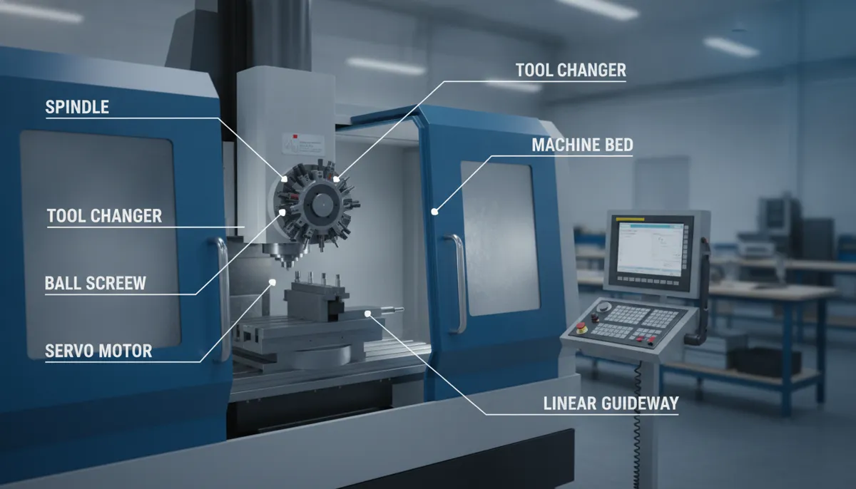
Welcome to the most complete CNC glossary A-Z for beginners on the web. Whether you’re a hobbyist just starting out, a purchasing agent evaluating machines, or a technician looking to sharpen your vocabulary, this comprehensive CNC terminology list covers 50+ essential CNC machining terms — from Axis to Zero Point — with plain-English definitions, real-world examples, and practical tips. Built on 15 years of hands-on CNC manufacturing experience at QFCNCMACHINE (est. 2010, Dongguan, China), and grounded in ISO 9001:2015 standards, this glossary is the reference guide we wish we’d had when we started.
Understanding CNC definitions is the first step to mastering CNC machining. Use the A–Z quick-jump navigation below to find any term instantly.
1. Why CNC Terminology Matters More Than Ever in 2026
The CNC industry is growing at a pace that makes technical literacy a genuine competitive advantage. According to Mordor Intelligence (2026), the global CNC machines market is valued at USD 79.14 billion in 2026 and is forecast to reach USD 105.70 billion by 2031, growing at a CAGR of 5.96% — driven by Industry 4.0 automation upgrades, EV powertrain demand, and aerospace re-equipment programs.[1]
Fortune Business Insights (2026) puts the figure even higher, valuing the global CNC machine tools market at USD 108.58 billion in 2026, projected to reach USD 251.61 billion by 2034 at a CAGR of 11.10%, with Asia Pacific holding a dominant 55.70% market share.[2]
Meanwhile, MarketsandMarkets (2023) highlights that the fastest-growing CNC applications are in high-precision sectors — automotive, aerospace, and medical devices — where misunderstanding a single term like “tolerance” or “datum” can mean the difference between a conforming part and a costly reject.[3]
In short: the operators, buyers, and engineers who master CNC vocabulary today are the ones who will lead their shops tomorrow.
2. Quick-Jump A–Z Navigation
Click any letter to jump directly to that section of the glossary:
3. Complete CNC Glossary A–Z: 50+ Terms Defined
A programming mode where all coordinates are measured from a fixed origin point (zero). Opposite of incremental programming. Most beginners start with absolute mode because it’s easier to visualize positions on a drawing.
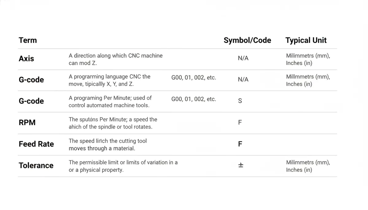
The direction of linear or rotational movement on a CNC machine. A 3-axis machine moves in X (left/right), Y (front/back), and Z (up/down). A 5-axis machine adds A and B rotational axes, enabling complex contoured parts like turbine blades to be machined in a single setup — reducing errors and setup time significantly.
A carousel or arm mechanism that automatically swaps cutting tools during a program without operator intervention. ATCs dramatically reduce cycle time on multi-operation parts. Capacity ranges from 8 to 120+ tools depending on the machine.
A G-code command that moves the tool in a circular arc. G02 = clockwise arc; G03 = counter-clockwise arc. Essential for machining radii, fillets, and circular pockets.
A cutting tool with a hemispherical tip, used for 3D contouring and curved surface machining. The ball nose allows smooth, scallop-free cuts on complex shapes. Common in mold making and aerospace component machining.
A single line of G-code in a CNC program. Each block typically contains one or more commands (e.g., N010 G01 X50.0 Y25.0 F200). Blocks are executed sequentially by the controller.
The process of enlarging and finishing an existing hole to precise diameter and tolerance using a single-point boring tool. Boring achieves tighter tolerances and better surface finish than drilling alone.
Software that translates a 3D CAD model into CNC toolpaths and G-code automatically. Popular CAM packages include Fusion 360, Mastercam, and SolidCAM. CAM software is the bridge between your design and the machine.
Software used to create 2D drawings or 3D models of parts before machining. Common tools include SolidWorks, AutoCAD, and CATIA. The CAD file is the starting point for every CNC job.
Unwanted vibration between the cutting tool and workpiece during machining, producing a wavy or rough surface finish. Caused by excessive tool overhang, incorrect spindle speed, or worn tooling. Reducing depth of cut or adjusting RPM usually eliminates chatter.
A manufacturing method where pre-programmed computer software dictates the movement of machine tools. CNC replaced manual machining with automated, repeatable precision — enabling mass production of complex parts with micron-level accuracy.
Fluid (water-soluble oil, synthetic, or straight oil) applied to the cutting zone to reduce heat, flush chips, and extend tool life. Flood coolant, mist coolant, and through-spindle coolant are the three main delivery methods.
A G-code function that offsets the tool path by the tool’s radius, allowing the programmed path to represent the part edge rather than the tool center. G41 = left compensation; G42 = right compensation. Incorrect compensation is a common beginner error that causes scrapped parts.
The total time required to complete one part from start to finish, including cutting, tool changes, and repositioning. Reducing cycle time is a key goal in production optimization.
A reference point, line, or plane from which all measurements on a part are taken. Establishing the correct datum is critical for ensuring parts meet drawing specifications. Miscommunicating datum locations between designers and machinists is a leading cause of rejection.
The distance the cutting tool penetrates into the workpiece material in a single pass. Measured in mm or inches. Deeper cuts remove more material per pass but increase cutting forces and risk of chatter.
A G-code command that pauses machine movement for a specified time (e.g., G04 P500 = 0.5 second pause). Used to allow the spindle to reach full speed before cutting, or to clean a hole bottom during drilling.
A CAD file format developed by Autodesk for 2D drawings. Widely used to transfer part geometry between CAD systems and CAM software. Most CNC routers and laser cutters accept DXF files directly.
A non-contact machining process that removes material using controlled electrical sparks. Ideal for hardened steels and complex internal geometries that are impossible to cut with conventional tools. Wire EDM and sinker EDM are the two main types.
A multi-flute rotary cutting tool used in CNC milling for profiling, slotting, and pocketing. Available in flat, ball nose, and corner-radius styles. Flute count (2–8) affects chip evacuation and surface finish.
A physical button or signal that immediately halts all machine movement and cuts power to drives. Every CNC machine must have an accessible E-Stop as a primary safety device. Pressing E-Stop does not reset the program — the operator must restart from a safe position.
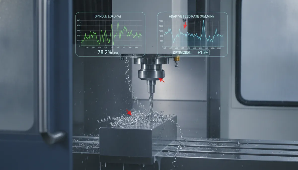
The speed at which the cutting tool moves through the workpiece, measured in mm/min or inches/min. Feed rate directly affects surface finish, tool life, and cycle time. Too fast causes tool breakage; too slow causes work hardening and poor finish. This is arguably the most important parameter for beginners to understand.
A device that holds and locates the workpiece on the machine table during cutting. Good fixture design ensures repeatability across multiple parts. Common fixtures include vises, clamps, custom jigs, and vacuum chucks.
A geometric tolerance that defines how flat a surface must be — the maximum allowable deviation from a perfect plane. Specified on engineering drawings using the flatness symbol (a parallelogram). Critical for sealing surfaces and precision assemblies.
The standard programming language that controls CNC machines. G-code commands (preparatory functions) tell the machine what motion to make. Common examples: G00 = rapid positioning, G01 = linear feed move, G02/G03 = arc moves, G28 = return to home. Learning the most-used 20 G-codes covers 90% of everyday programming needs.
An international engineering drawing standard (ASME Y14.5 / ISO 1101) that uses symbols to define the allowable variation in form, orientation, location, and runout of part features. Understanding GD&T is essential for communicating with suppliers and inspectors.
Software that virtually runs a CNC program to check for errors, collisions, and incorrect toolpaths before the machine cuts real material. Tools like Vericut, NC Viewer, and CAM-integrated simulators prevent costly crashes.
The machine’s reference zero point, typically located at the maximum travel limits of each axis. Returning to home (G28) re-establishes the machine’s coordinate system after a power cycle or E-Stop event.
A machining center where the spindle is oriented horizontally. HMCs excel at multi-sided machining using a rotary pallet, allowing gravity to assist chip evacuation. Preferred for high-volume production of prismatic parts.
A programming mode where each coordinate is measured relative to the current tool position, not a fixed origin. Useful for repetitive patterns and drilling cycles. Must be used carefully — errors accumulate if a previous move was incorrect.
The method by which a CNC controller calculates the path between two programmed points. Linear interpolation (G01) moves in a straight line; circular interpolation (G02/G03) moves in an arc. Advanced controllers also support helical and NURBS interpolation.
Units for expressing feed rate. IPM = linear feed speed; IPR = feed per spindle revolution (used in turning). Understanding the relationship between IPM, IPR, and RPM is fundamental to calculating correct cutting parameters.
Manual movement of a CNC axis using the machine’s control panel or handwheel, without running a program. Used for setting work offsets, probing, and positioning the tool before a job starts. Jog speed is adjustable — always start slow.
A device that guides a cutting tool to a specific location on a workpiece. Unlike a fixture (which holds the part), a jig actively guides the tool. Drill jigs are the most common type in CNC shops.
The width of material removed by a cutting process. In CNC laser cutting and waterjet, kerf is the slot width left by the beam or jet. Kerf compensation must be applied in the program to achieve the correct finished part dimensions.
A mathematical representation of a machine’s physical geometry and axis relationships used in simulation software. Accurate kinematic models enable reliable collision detection and post-processor verification before cutting.
A programmed approach and exit path that brings the tool smoothly into and out of the cut, preventing entry marks on finished surfaces. Tangential arc lead-ins are standard practice for profile milling.
The most common CNC motion command — moves the tool in a straight line at a programmed feed rate. Syntax: G01 X100.0 Y50.0 F300. Used for all straight-line cutting moves.
G-code commands that control machine functions rather than motion. Common M-codes: M03 = spindle on clockwise, M05 = spindle stop, M06 = tool change, M08 = coolant on, M30 = program end and rewind. M-codes work alongside G-codes in every CNC program.
A CNC machine tool capable of multiple operations (milling, drilling, boring, tapping) in a single setup, equipped with an ATC. VMCs (vertical) and HMCs (horizontal) are the two main types. The machining centers segment leads the global CNC market by product type.[3]
A G-code or M-code that remains active until cancelled or replaced by another command. For example, G01 stays active for all subsequent moves until G00 or G02 is programmed. Understanding modal vs. non-modal commands prevents unexpected machine behavior.
The predecessor to CNC — machines controlled by punched tape rather than a computer. Modern CNC evolved from NC in the 1970s. The term “NC” is still sometimes used interchangeably with CNC in older documentation.
The process of arranging multiple part profiles on a sheet of material to minimize waste. CAM software performs automatic nesting for laser cutting, plasma cutting, and waterjet operations. Good nesting can reduce material waste by 15–30%.
A value stored in the CNC controller that compensates for the actual position or size of a tool or workpiece. Tool length offset accounts for different tool lengths; work offset (G54–G59) defines the part zero position on the machine table. Incorrect offsets are the #1 cause of beginner crashes.
The reference point (X0, Y0, Z0) from which all programmed coordinates are measured. Set by the operator using a probe or edge finder before running the program. Also called “work zero” or “datum point.”
A fixture plate that holds workpieces and can be automatically swapped in and out of the machining zone. Pallet changers enable “lights-out” machining — loading the next part while the current one is being cut.
Software that converts generic CAM toolpaths into machine-specific G-code formatted for a particular CNC controller (e.g., Fanuc, Siemens, Haas). Using the wrong post-processor for your machine is a common source of program errors.
Using a touch-trigger or scanning probe to automatically measure workpiece position, tool length, or part features. Probing eliminates manual setup errors and enables in-process quality control without removing the part from the machine.
The arithmetic mean of surface profile deviations, measured in micrometers (µm) or microinches (µin). Ra is the most common surface finish specification. A typical machined surface is Ra 1.6 µm; a ground surface may be Ra 0.4 µm or finer.
The fastest possible axis movement, used for positioning the tool between cuts — not for cutting. G00 moves at the machine’s maximum speed (often 20–60 m/min). Never program G00 into a workpiece — always retract the tool first.
The total deviation of a rotating surface from its true axis of rotation, measured with a dial indicator. Excessive runout in a tool holder causes vibration, poor surface finish, and premature tool wear. Acceptable runout for precision work is typically under 0.005 mm.
The rotational speed of the machine spindle, measured in revolutions per minute. Optimal spindle speed depends on the cutting tool diameter, material, and desired surface finish. For aluminum: 10,000–15,000 RPM is typical; for hardened steel: 1,000–3,000 RPM. Too high burns material; too low causes chatter.
The lateral distance between adjacent toolpath passes in a milling operation, expressed as a percentage of tool diameter. A 50% step-over is standard for roughing; 10–15% for finishing passes to achieve smooth surfaces.
A reusable block of G-code called from the main program using M98. Subprograms eliminate repetitive code for repeated features like hole patterns or identical pockets, making programs shorter and easier to edit.
The texture and smoothness of a machined surface, specified by Ra value or a finish symbol on the drawing. Influenced by feed rate, spindle speed, tool geometry, and material. Achieving the specified surface finish is a key quality requirement in aerospace and medical machining.
The permissible variation in a dimension, expressed as ±0.XX mm or as upper/lower limits. Tighter tolerances require more precise machines, slower feeds, and more careful setup. Communicating tolerances clearly to your supplier prevents costly rejection. ISO 286 defines standard tolerance grades (IT grades).
A value stored in the controller that compensates for the actual length or radius of a cutting tool. Tool length offsets (H values) ensure the Z-axis zero is correctly referenced to each tool tip. Radius offsets (D values) work with cutter compensation (G41/G42).
The process of aligning the machine spindle perpendicular to the table surface. An out-of-tram spindle produces a “cusp” or ridge on face-milled surfaces. Tramming is done with a dial indicator swept in a circle around the spindle axis.
A CNC machining process where the workpiece rotates against a stationary cutting tool to produce cylindrical shapes. Performed on a CNC lathe or turning center. Contrast with milling, where the tool rotates and the workpiece is stationary.
A custom coordinate system defined by the operator to align the program zero with a convenient feature on the part. Using UCS (or work offsets G54–G59) allows multiple parts to be set up on the table simultaneously with separate zero points.
Up-cut (conventional) milling moves the tool against the feed direction; down-cut (climb) milling moves with it. Climb milling produces better surface finish and longer tool life on rigid machines. Conventional milling is safer on older machines with backlash.
The maximum volume of space within which a CNC machine can move its tool — defined by X, Y, and Z travel limits. Choosing a machine with an insufficient work envelope is a common and costly beginner mistake. Always verify your largest part fits within the envelope with clearance for fixtures.
Stored coordinate values that define the location of the part zero relative to the machine zero. G54 is the most commonly used work offset. Multiple offsets allow different parts or fixtures to be set up simultaneously.
The collective term for all methods and devices used to secure a workpiece during machining — vises, clamps, chucks, collets, magnetic chucks, and vacuum fixtures. Proper workholding is critical for part accuracy and operator safety.
The absolute reference position of the machine (machine zero) or the programmed origin of the part (part zero / work zero). Establishing the correct part zero before running a program is one of the most critical setup steps. An error of even 0.1 mm in zero-setting can scrap an entire batch.
The vertical axis on a vertical machining center (VMC), representing the depth of cut direction. On a lathe, Z is the axis parallel to the spindle centerline. The Z-axis is typically the most critical for controlling depth of cut and tool length compensation.
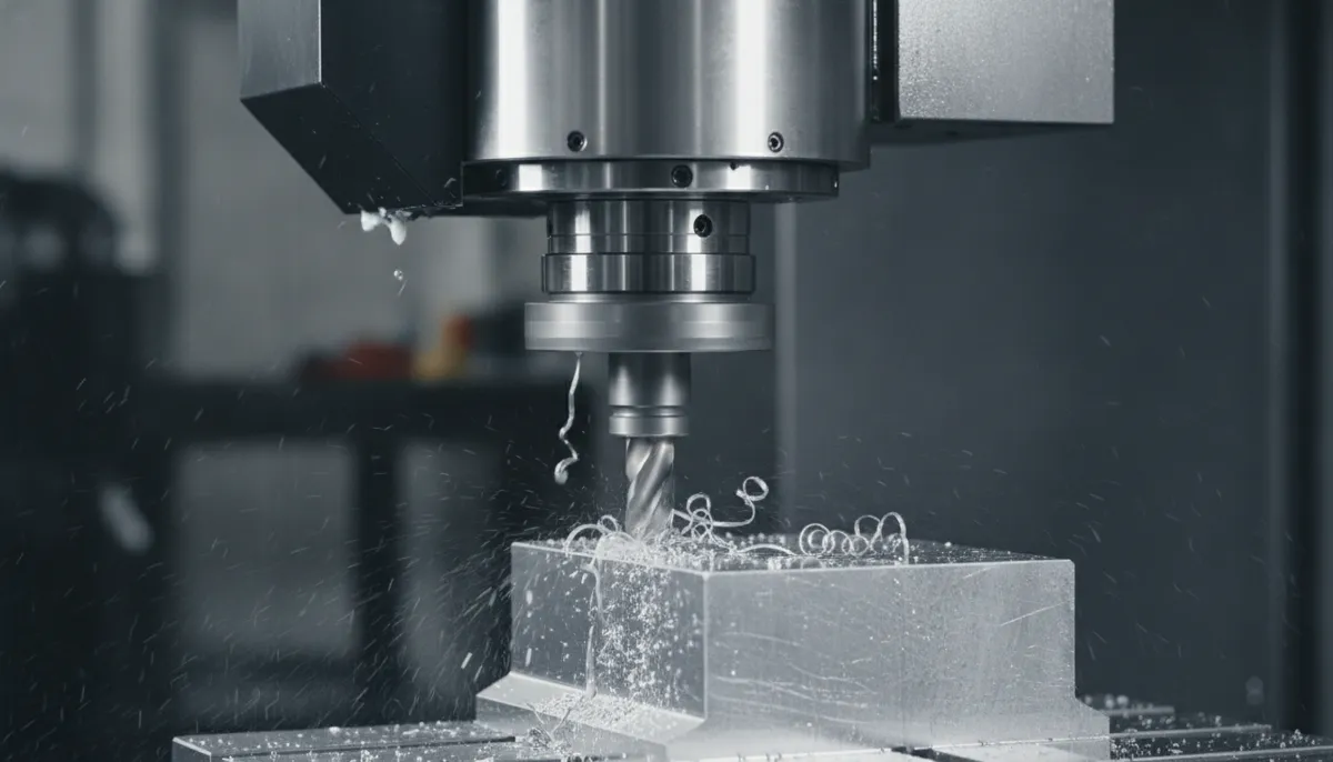
4. CNC Milling vs. Turning: Key Terms Compared
Two of the most common CNC processes use overlapping but distinct terminology. Here’s a quick reference:
| Term / Parameter | CNC Milling | CNC Turning |
|---|---|---|
| What rotates? | Cutting tool (end mill, drill) | Workpiece (chuck-held) |
| Primary shapes produced | Flat surfaces, pockets, profiles, 3D contours | Cylindrical, conical, threaded parts |
| Feed rate unit | mm/min (IPM) | mm/rev (IPR) |
| Spindle speed | RPM (tool rotation) | RPM or CSS (constant surface speed) |
| Depth of cut direction | Axial (Z) and radial (X/Y) | Radial (X) and axial (Z) |
| Common G-codes | G00, G01, G02, G03, G41, G42 | G00, G01, G96 (CSS), G97 (RPM), G71 (rough cycle) |
| Workholding | Vise, clamps, fixture plate | 3-jaw chuck, collet, live center |
| Surface finish spec | Ra (µm), flatness, perpendicularity | Ra (µm), cylindricity, runout |
5. Real-World Use Cases: How CNC Terminology Knowledge Pays Off
Case 1 — Selecting the Right Machine
A job shop in the US was evaluating a 3-axis vs. 5-axis machining center. By understanding terms like “simultaneous 5-axis,” “work envelope,” and “axis configuration,” the buyer correctly identified that their aerospace bracket required true 5-axis simultaneous motion — not just 3+2 positioning. They avoided purchasing an undersized machine and saved significant rework costs on their first production run.
Case 2 — Writing Error-Free G-Code
A beginner hobbyist in Germany was scrapping 20% of parts due to incorrect cutter compensation (G41/G42). After studying the glossary entries for “Cutter Compensation,” “Tool Offset,” and “Work Offset,” he corrected his program logic and reduced scrap to under 2% — saving both material and time.
Case 3 — Supplier Communication in Southeast Asia
A purchasing agent at an electronics manufacturer in Malaysia needed to specify surface finish and tolerance requirements to a new CNC supplier. Using the glossary definitions for “Ra,” “Tolerance,” “Datum,” and “GD&T,” she communicated requirements precisely, reducing first-article rejection rates by over 15% compared to the previous supplier relationship.
6. What Our Customers Say
“I was completely new to CNC when I started my small parts business in Ohio. QFCNCMACHINE’s glossary was the first resource that actually explained terms like ‘work offset’ and ‘cutter compensation’ in plain English — not just textbook definitions. Within two weeks I went from crashing tools to running consistent jobs. I keep it bookmarked and refer to it constantly.”
“As a CNC trainer at a vocational college in Stuttgart, I recommend this glossary to every new student on day one. The A-Z format with real-world examples makes abstract concepts like ‘interpolation’ and ‘tramming’ immediately understandable. It’s become a standard reference in our curriculum alongside our official textbooks.”
“Our mold shop in Penang supplies injection mold tooling to electronics OEMs across Southeast Asia. Miscommunication with customers about tolerances and surface finish specs used to cost us rework time every month. After sharing QFCNCMACHINE’s glossary with our sales and engineering teams, everyone speaks the same language. Rejection rates on first-article submissions dropped noticeably within the first quarter.”
7. Pros and Cons of Learning CNC Terminology
✅ Pros
- Better communication with machinists, engineers, and suppliers worldwide
- Faster troubleshooting — identify the root cause of errors by name
- Improved part quality through correct parameter selection (feed rate, RPM, DOC)
- Reduced material waste — fewer scrapped parts from programming errors
- Stronger supplier relationships — shared vocabulary prevents misunderstandings
- Faster machine selection — understand spec sheets without guesswork
- Foundation for advanced learning: CAM programming, GD&T, 5-axis machining
❌ Cons
- Initial learning curve — 50+ terms can feel overwhelming at first
- Some terms vary by controller brand (Fanuc vs. Siemens vs. Haas dialects)
- Terminology alone doesn’t replace hands-on machine time
- GD&T and ISO standards require additional study beyond basic glossary terms
8. Frequently Asked Questions
What is the difference between CNC milling and turning?
CNC milling uses a rotating cutting tool to remove material from a stationary workpiece, producing flat surfaces, pockets, profiles, and 3D contours. CNC turning rotates the workpiece against a stationary tool, producing cylindrical, conical, and threaded parts. Both processes are covered in detail in this CNC glossary A-Z. See the comparison table in Section 4 for a side-by-side breakdown of key terms.
Do I need to know G-code to operate a CNC machine?
Modern CNC machines often use conversational programming interfaces or CAM software (Fusion 360, Mastercam) that generate G-code automatically. However, understanding basic G-code — especially G00, G01, G02, G41, G54, and M-codes — allows you to edit programs, troubleshoot errors, and override incorrect moves safely. We recommend every operator learn at least the 20 most common G and M codes.
How long does it take to learn CNC terminology?
Most beginners can learn the top 20–30 essential terms within one week with 20 minutes of daily study. The full A-Z glossary of 50+ terms typically takes 2–3 weeks to internalize. Using terms in context — while actually running a machine or writing a program — accelerates retention significantly.
What is the most important CNC term for a beginner?
“Feed Rate” is arguably the most critical parameter for beginners to understand. It controls how fast the tool moves through material, directly affecting tool life, surface finish, and part accuracy. Incorrect feed rate is the leading cause of tool breakage and scrapped parts for new operators. Learn how to calculate feed rate using the formula: Feed Rate (mm/min) = RPM × Number of Flutes × Chip Load per Flute.
Is this CNC glossary suitable for advanced users too?
Yes. While designed with beginners in mind, this glossary includes advanced terms such as GD&T, Kinematic Model, Probing, Nesting, Post-Processor, and Pallet Changers that even experienced machinists and engineers reference regularly. It serves as a comprehensive quick-reference for all skill levels.
What is QFCNCMACHINE’s warranty and return policy?
All QFCNCMACHINE equipment comes with a 2-year manufacturer’s warranty covering defects in materials and workmanship. Returns are supported for confirmed quality issues. We do not support no-reason returns without a verified quality defect. Contact us at bella@qfcncmachine.com or +86 151 1824 3737 for any after-sales support.
Ready to Put Your CNC Knowledge Into Practice?
QFCNCMACHINE has been supplying precision CNC equipment to 750+ customers across Europe, North America, and Southeast Asia since 2010. Talk to our team for a personalized machine recommendation — or just ask us anything about CNC terminology.
References
- Mordor Intelligence, CNC Machines Market Size & Share Analysis — Growth Trends and Forecast (2026–2031), 2026. View Report →
- Fortune Business Insights, CNC Machine Market Size, Share & Industry Analysis — Regional Forecast 2026–2034, July 2026. View Report →
- MarketsandMarkets, CNC Machine Market Size, Share & Industry Trends Growth Analysis Report — Global Forecast to 2028, October 2023.