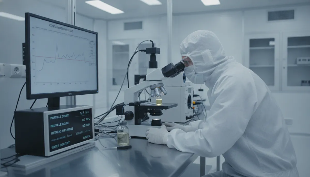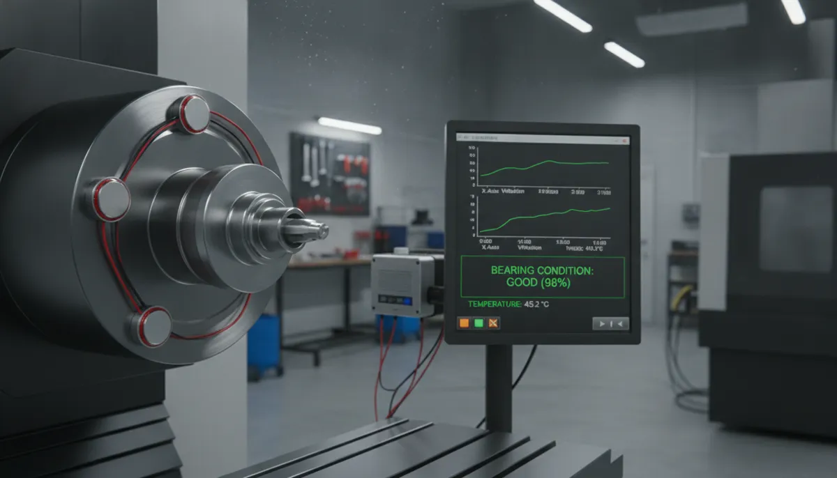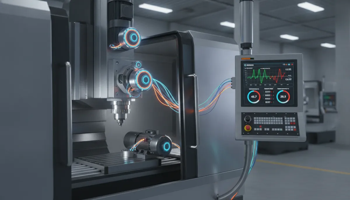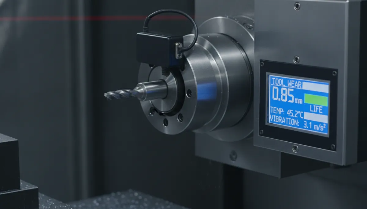
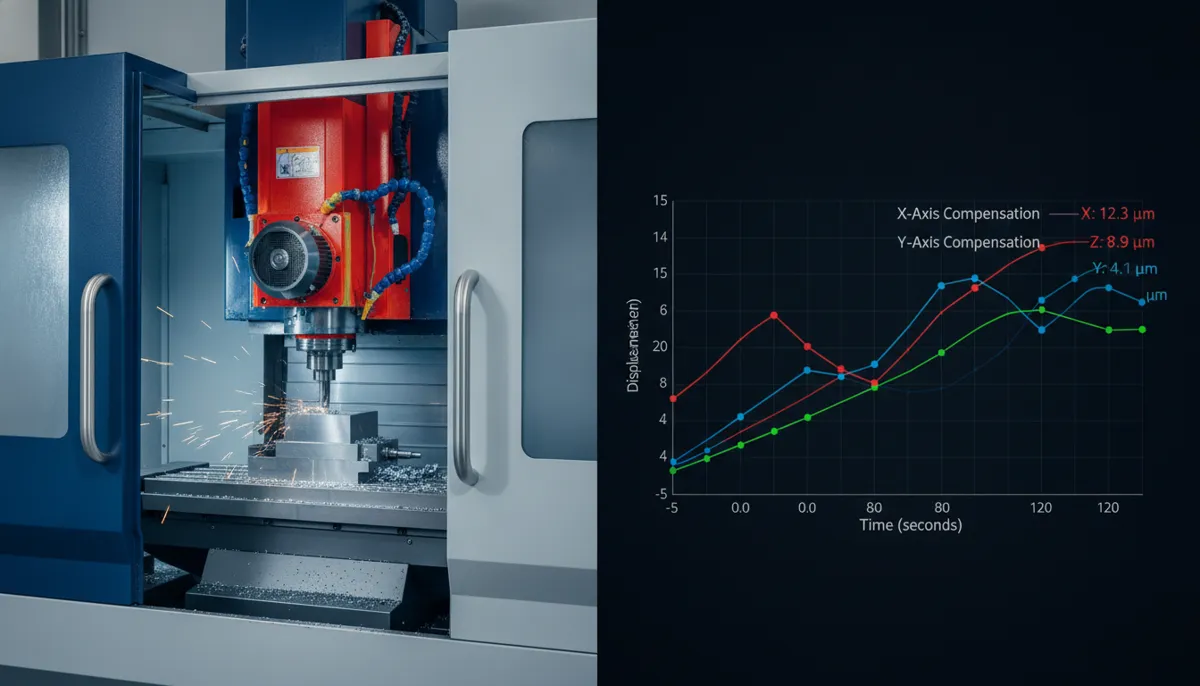
CNC thermal compensation helps manufacturers reduce the effect of heat-related machine movement on dimensional accuracy. During machining, heat can be generated by spindle bearings, motors, ball screws, guideways, coolant systems, cutting loads, and changing ambient temperatures. As the machine structure expands or shifts, the tool center point may move relative to the workpiece, affecting critical dimensions, surface finish, and repeatability.
For precision machining teams, thermal stability is not achieved by one sensor or one correction value. It requires a structured process: identify relevant heat sources, collect reliable temperature and machine-state data, establish a baseline, validate the error model, and apply compensation through an approved CNC control method. QiaoFeng supports practical CNC thermal compensation projects for machining centers where thermal drift affects quality, setup time, or process consistency.
Established in 2010, QiaoFeng has served more than 750 customers across Europe, the Americas, and Southeast Asia. From Dalingshan Town, Dongguan, Guangdong, China, our team helps manufacturers evaluate CNC equipment, monitoring options, and precision-focused improvement projects.
1. Why CNC Thermal Compensation Matters
Machine tools do not operate at a constant temperature. A spindle may heat during warm-up and high-speed cutting, ball screws may warm under repeated axis movement, and coolant temperature may change across a production shift. Environmental conditions can also influence the machine bed, column, and surrounding structure. These effects can create time-varying displacement that static geometric compensation alone cannot fully address.
Published machine-tool research identifies thermal behavior as a significant source of precision variation and highlights the importance of measuring, modeling, and reducing thermally induced errors. The exact contribution of thermal effects varies by machine architecture, duty cycle, ambient control, maintenance condition, and machining process. [2] [3]
The machining-center market continues to develop alongside demand for higher productivity, automation, and precision. For facilities producing close-tolerance automotive, aerospace, mold, medical, and general engineering components, a validated CNC thermal compensation workflow can support more stable dimensional performance during long machining cycles and changing operating conditions. [1]
2. Main Sources of Thermal Error in CNC Machines
Effective CNC thermal compensation starts with understanding where heat is generated and how it affects the machine structure. The most relevant sources differ by machine model and process, but the following areas are commonly assessed during a thermal stability review.
- Spindle system: Bearings, motor losses, lubrication, high-speed operation, and toolholder condition can influence spindle temperature and axial or radial displacement.
- Ball screws and servo axes: Friction, preload, nut condition, duty cycle, and servo loading can generate heat that affects axis positioning behavior.
- Machine structure: The column, bed, saddle, and headstock can respond differently to internal heat and ambient temperature changes.
- Coolant and lubrication systems: Coolant temperature, flow consistency, chiller performance, and lubricant condition may affect thermal equilibrium.
- Production environment: Shift changes, doors opening, sunlight, airflow, nearby equipment, and seasonal temperature variation can affect machine stability.
- Machining process: Material type, spindle speed, feed rate, tool engagement, cycle time, and idle periods all influence the heat profile.
3. How CNC Thermal Compensation Works
3.1 Sensor-Based Temperature Data Collection
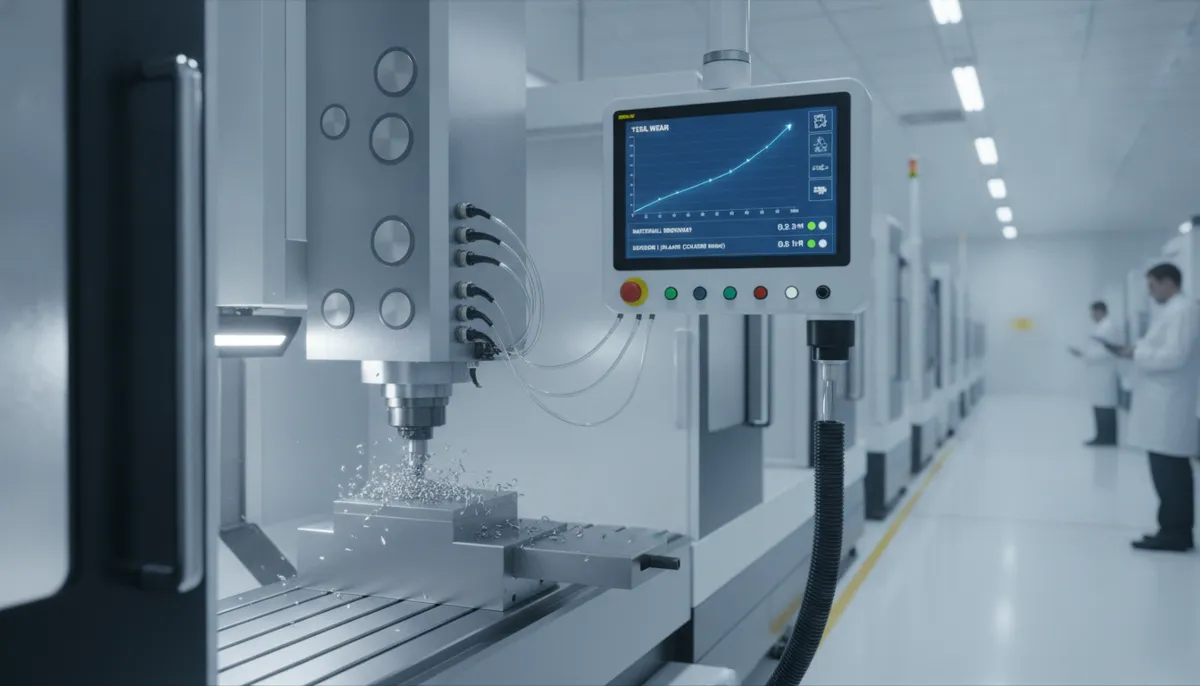
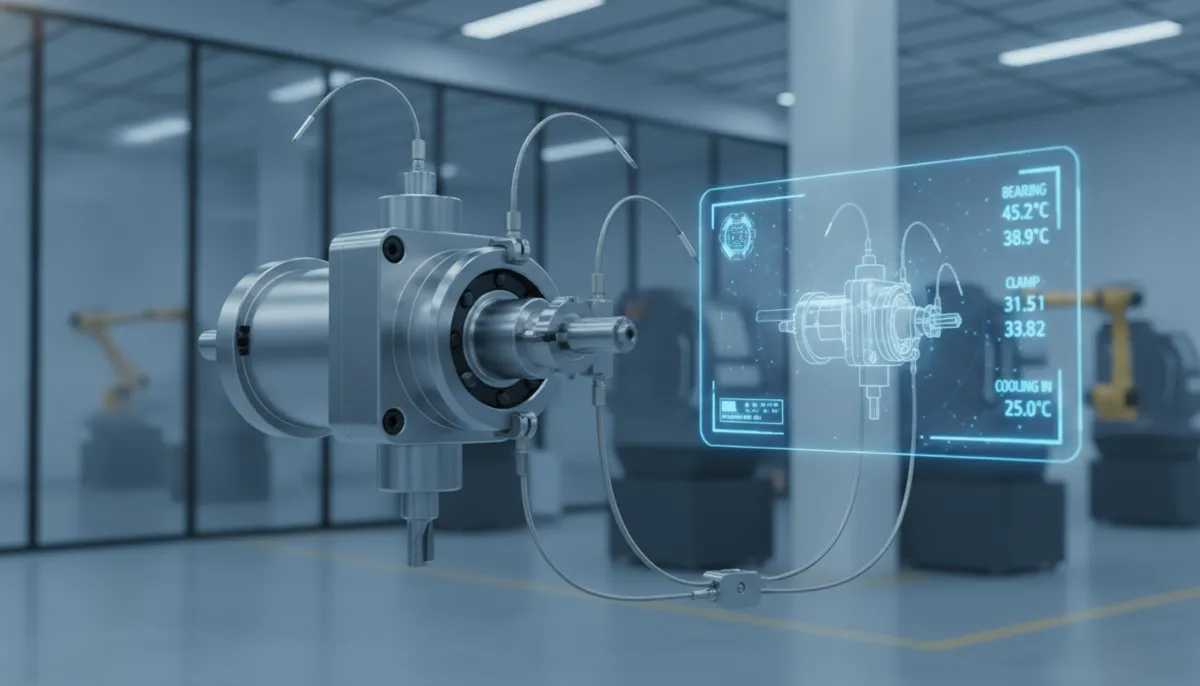
A sensor layout should be selected based on the machine’s thermal behavior rather than using a fixed number of sensors for every project. Temperature sensors may be placed near relevant locations such as the spindle housing, motor area, ball screw support zones, column, bed, coolant circuit, and machine environment. PT100 RTD sensors are commonly used in industrial temperature measurement because they can provide stable, repeatable readings when correctly installed and calibrated.
The goal is not simply to collect more data. It is to collect data from locations that meaningfully correlate with thermal displacement. During a CNC thermal compensation assessment, the most useful sensor positions should be identified through machine structure, duty-cycle, and validation testing.
3.2 Thermal Error Modeling and Baseline Testing
After data collection begins, the machine should be evaluated through representative warm-up, idle, cutting, and cool-down conditions. The resulting temperature and displacement data can be used to establish a baseline and develop a model of how the machine responds to thermal change.
Depending on the project, the model may use regression methods, empirical temperature-displacement relationships, data-driven algorithms, or a hybrid approach. No single method is best for every machine. A model that performs well under one set of spindle speeds, ambient temperatures, and cutting loads must still be validated across the operating conditions that matter to the customer.
3.3 Applying Compensation Through an Approved Control Method
Once validated, CNC thermal compensation may be applied through controller offsets, approved macro functions, external supervisory logic, or other controller-compatible methods. Retrofit feasibility depends on the CNC model, machine builder configuration, available communication interfaces, access permissions, controller options, and plant safety requirements.
For this reason, compatibility should be confirmed during a technical assessment. Fanuc, Siemens, Heidenhain, Mitsubishi, and other control platforms may offer different integration possibilities depending on the controller generation and installed options. In some cases, a monitoring-and-recommendation workflow may be more suitable than automatic offset writing.
3.4 Validation, Review, and Recalibration
A thermal model should be validated using a suitable measurement process, such as probing cycles, laser interferometer testing, ballbar testing, calibrated artifacts, or finished-part measurement. Results should be compared before and after compensation under defined conditions. Recalibration may be needed after major service, spindle replacement, machine relocation, structural repair, changes in coolant management, or substantial process changes.
4. Typical Applications for CNC Thermal Compensation
4.1 Extended Production Runs for Automotive Components
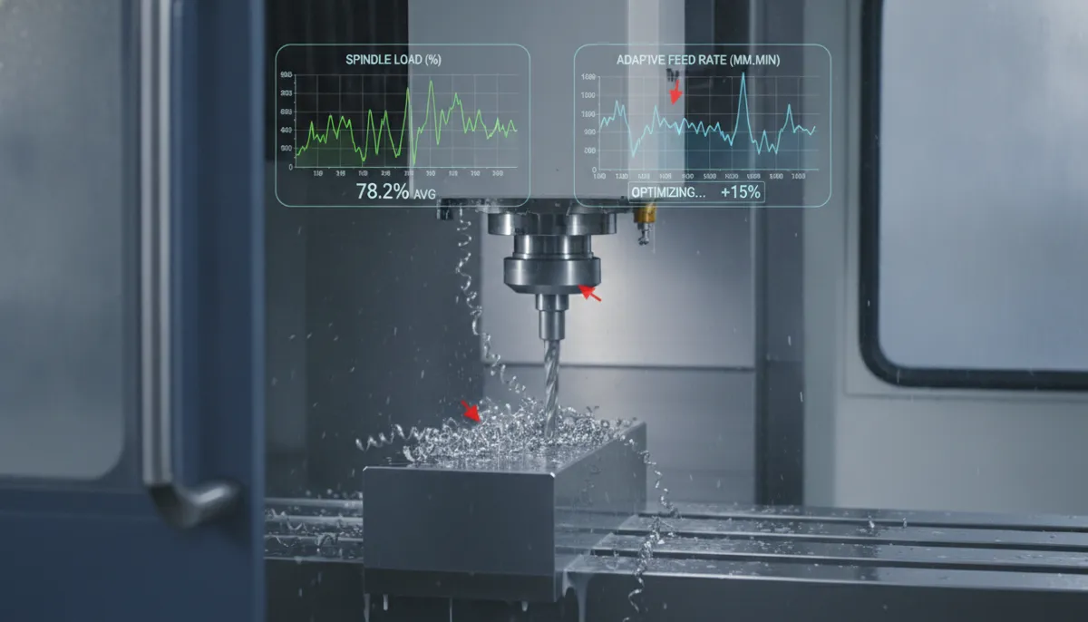
High-volume automotive component production often involves repeated cycles over long shifts. When dimensional variation changes between machine warm-up and stabilized operation, temperature-related movement may be one contributing factor. A sensor-based monitoring and CNC thermal compensation project can help teams compare dimensional trends with spindle load, coolant temperature, axis activity, and ambient conditions.
4.2 Mold, Die, and Precision Tooling Machining
Mold and die manufacturers frequently machine cavities, electrodes, inserts, and contour surfaces where repeatability matters across long finishing operations. In these environments, thermal behavior should be considered alongside tool deflection, workholding stability, machine geometry, and inspection strategy. Compensation can support a more stable process when the thermal response has been properly characterized.
4.3 Aerospace and High-Value Precision Components
Aerospace suppliers and other high-value component manufacturers may require structured process-capability evidence for critical features. CNC thermal compensation can support that objective by providing a documented approach to monitoring thermal conditions and validating machine behavior. It does not replace quality-system requirements, first-article inspection, process validation, or customer-specific compliance obligations.
5. CNC Thermal Compensation Solution Evaluation Checklist
When comparing thermal compensation solutions, focus on measurable engineering requirements instead of generic claims about accuracy. The following checklist can help maintenance and process teams assess suitability.
| Evaluation Area | Key Question | Recommended Evaluation Method |
|---|---|---|
| Machine suitability | Is thermal drift a meaningful contributor to the current quality issue? | Review part measurements, warm-up behavior, spindle usage, axis performance, and ambient conditions. |
| Sensor layout | Are sensors positioned at relevant thermal nodes? | Use machine structure and thermal test results to select meaningful locations. |
| Model quality | Does the model remain reliable across expected operating conditions? | Validate with multiple speeds, loads, production cycles, and temperature conditions. |
| Controller integration | Can compensation be applied safely through the available CNC interface? | Confirm controller model, options, permissions, communication method, and safety review. |
| Verification method | How will improvement be measured? | Define probing, laser, ballbar, artifact, or part-inspection procedures before deployment. |
| Maintenance workflow | Who reviews alerts, validates readings, and manages recalibration? | Create a documented process involving maintenance, process engineering, and quality teams. |
6. Illustrative Industry Testimonials
The following quotations are illustrative examples based on common precision-machining use cases in QiaoFeng’s export markets. They are not presented as verified customer endorsements and should be replaced with customer-authorized feedback before use as formal case studies.
“Our team needed a better way to understand why critical dimensions changed between the beginning and end of a production shift. By comparing machine temperature trends with inspection data, we gained a more structured basis for deciding when to investigate spindle, coolant, and warm-up behavior.”
“For mold inserts and finishing work, consistency is as important as nominal accuracy. A thermal monitoring and compensation workflow gave our engineers more visibility into machine behavior during extended machining cycles and helped us standardize our validation process.”
“We operate CNC machines with different controller generations, so we needed a practical retrofit approach. Starting with temperature data and verification testing allowed us to assess the potential value before expanding the program to more machines.”
7. Benefits and Implementation Considerations
Potential Benefits
- Supports more stable machining performance during changing thermal conditions.
- Helps engineers investigate thermal drift using measurable machine data.
- May reduce avoidable rework when heat-related variation is a confirmed cause.
- Creates a documented basis for warm-up, monitoring, and validation procedures.
- Can be evaluated for retrofit applications, subject to machine compatibility.
Implementation Considerations
- Compensation cannot correct all sources of machining error.
- Sensor placement, installation quality, and data validation are critical.
- Machine wear, poor geometry, tooling issues, and weak workholding need separate action.
- Models require validation under representative production conditions.
- Automatic offset changes require controller, safety, and process approval.
8. Frequently Asked Questions
How is CNC thermal compensation different from static geometric compensation?
Static geometric compensation addresses errors that are relatively stable, such as screw pitch error, backlash, or squareness. CNC thermal compensation addresses changes that occur as machine temperatures change over time. In practice, both approaches may be needed because a machine can have static geometric errors and time-varying thermal displacement at the same time.
What sensors are normally used for thermal compensation?
PT100 RTD temperature sensors are commonly used because they can provide stable industrial temperature measurement when properly installed. Depending on the project, other inputs may include ambient sensors, coolant temperature sensors, spindle load, servo load, axis activity, and machine-state data. Final sensor selection should be based on the machine design and validation plan.
Can CNC thermal compensation be retrofitted to older machines?
In many cases, yes. External sensors can often be installed without major machine modification. However, automatic compensation feasibility depends on the CNC controller model, available interfaces, software options, access permissions, and approved method for applying offsets. A site assessment is required before confirming compatibility.
Can thermal compensation guarantee sub-micron accuracy?
No responsible provider should guarantee sub-micron finished-part accuracy for every machine and application. Compensation can reduce verified thermal effects, but final accuracy depends on machine condition, geometry, environment, tooling, workholding, cutting process, measurement uncertainty, and operator procedures.
How is the result validated?
Validation may use on-machine probing, laser interferometer testing, ballbar testing, calibrated artifacts, or finished-part inspection. The method should be agreed before implementation so that performance is measured against repeatable conditions and meaningful acceptance criteria.
What warranty and refund policy applies?
Applicable QiaoFeng hardware is covered by a 2-year warranty under the relevant warranty terms. Refund support may be available for verified product quality issues. Returns due to change of mind or other non-quality reasons are not supported. Please contact QiaoFeng before purchase to confirm the applicable technical scope, warranty, and service conditions.
Discuss Your CNC Thermal Compensation Project
Tell us about your machine type, controller, part tolerance, production cycle, current measurement method, and thermal stability concern. The QiaoFeng team can help you evaluate a practical monitoring, validation, and compensation approach.
References
- Mordor Intelligence, Machining Centers Market Size, Share & Growth Trends Report, 2024.
- Mayr, J. et al., Thermal Issues in Machine Tools, CIRP Annals, Volume 61, Issue 2, 2012.
- Ramesh, R., Mannan, M. A., and Poo, A. N., Error Compensation in Machine Tools—A Review Part II: Thermal Errors, International Journal of Machine Tools and Manufacture, Volume 40, Issue 9, 2000.
- U.S. Department of Energy, Federal Energy Management Program, Operations & Maintenance Best Practices Guide, Release 3.0.
- National Institute of Standards and Technology, NIST SP 800-82 Rev. 3: Guide to Operational Technology Security.
References are provided for general industry and technical context. Thermal compensation capability, controller compatibility, validation methods, and expected results must be assessed for each individual machine, process, and production environment.