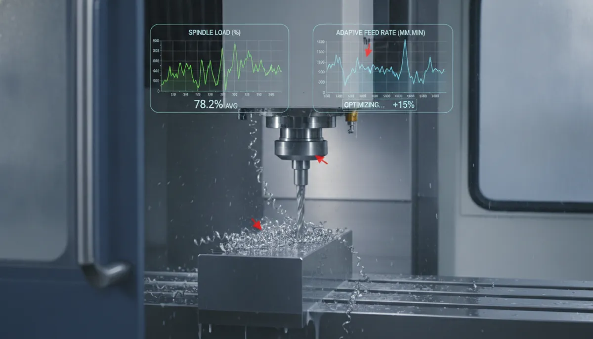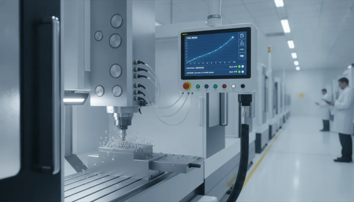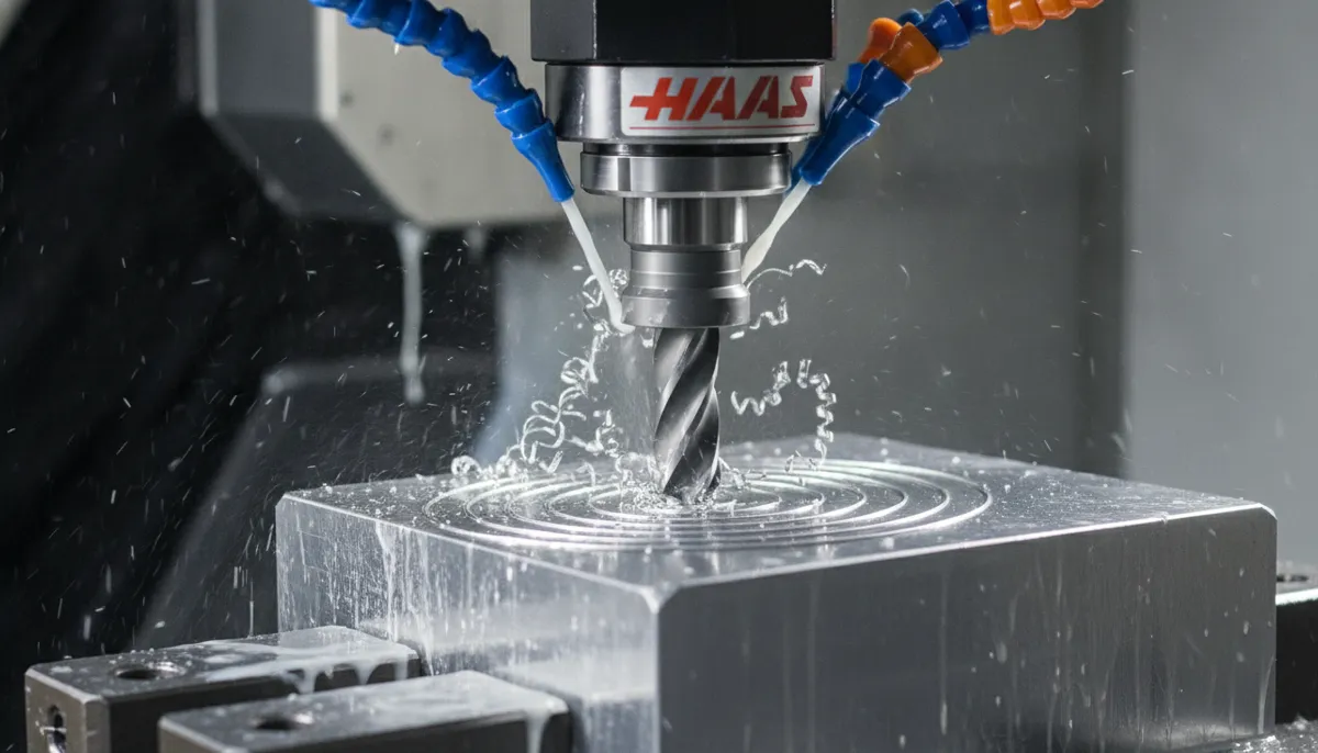
If you’re new to CNC machining, understanding CNC toolpath strategies is the single most impactful skill you can develop for improving part quality and production efficiency. A CNC toolpath is the programmed route your cutting tool follows to remove material from a workpiece — it determines everything from surface finish and dimensional accuracy to cycle time and tool life. Get it right, and your machine runs fast, clean, and reliably. Get it wrong, and you’ll face excessive tool wear, poor surface finish, and wasted material. At QiaoFeng CNC, founded in 2010 and trusted by 750+ customers across Europe, North America, and Southeast Asia, we’ve spent 15 years helping manufacturers master CNC toolpath optimization on machines ranging from 3-axis mills to full 5-axis machining centers. This guide covers definitions, types, real G-code examples, key parameters, and best practices.
1. Why CNC Toolpath Optimization Matters in Today’s Market
The global CNC machining industry is expanding rapidly, placing increasing pressure on manufacturers to maximize machine utilization and minimize cycle time. According to Mordor Intelligence’s Machining Centers Market Report, the global machining centers market is valued at USD 23.67 billion in 2026 and is projected to grow at a CAGR of 5.37% through 2031. Meanwhile, Fortune Business Insights values the broader CNC machine tools market at USD 101.22 billion in 2025, with continued growth forecast through 2034.
As manufacturers adopt higher-mix, lower-volume production strategies and tighter delivery windows, CNC toolpath efficiency has become a direct competitive differentiator. According to MarketsandMarkets, the CNC market is set to grow from USD 67.5 billion in 2023 to USD 80.4 billion by 2028 — driven largely by demand for smarter, faster machining strategies. In this environment, shops that master advanced toolpath techniques such as adaptive clearing, trochoidal milling, and high-speed finishing gain a measurable edge over competitors still relying on conventional approaches.
2. What Is a CNC Toolpath? Definition and Core Concepts
A CNC toolpath is the precise three-dimensional trajectory that a cutting tool follows relative to the workpiece, as defined in your CAM (Computer-Aided Manufacturing) software and output through your post processor as G-code. Every movement the tool makes — rapids, plunges, cutting passes, retracts — is part of the toolpath.
A toolpath is defined by several key parameters that every machinist must understand:
- Stepover (Radial Depth of Cut / ae) — How far the tool moves sideways between passes, expressed as a percentage of tool diameter. Roughing: 50–80%. Finishing: 3–10%.
- Step-down (Axial Depth of Cut / ap) — How deep the tool cuts per pass in the Z axis. Roughing: 0.5–2× tool diameter. Finishing: 0.1–0.3mm.
- Feed Rate (F) — The speed at which the tool moves through the material, in mm/min or inch/min.
- Spindle Speed (S) — Tool rotation speed in RPM, calculated from cutting speed (Vc) and tool diameter.
- Lead-In / Lead-Out — The entry and exit motion of the tool into and out of the cut. Smooth arcing lead-ins prevent tool shock and improve surface finish.
- Climb vs. Conventional Milling — Climb milling (tool rotation matches feed direction) produces better surface finish and is preferred for finishing. Conventional milling is sometimes used for roughing in difficult materials.
3. Types of CNC Toolpaths: Roughing vs. Finishing
Every machined part requires at least two categories of CNC toolpath: roughing to remove bulk material quickly, and finishing to achieve the final dimensions and surface quality. Understanding when and how to use each is fundamental to efficient machining.
3.1 CNC Roughing Toolpath
A CNC roughing toolpath prioritizes material removal rate (MRR) over surface quality. The goal is to remove as much stock as possible as fast as possible, leaving a consistent amount of material (typically 0.3–1.0mm) for the finishing pass. Roughing uses larger stepovers (50–80% of tool diameter), larger step-downs, and higher chip loads.
Common roughing strategies include:
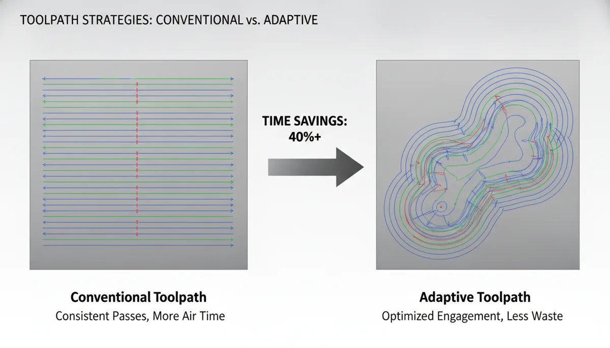
- Adaptive Clearing (Dynamic Milling) — Maintains a constant chip load by continuously adjusting the toolpath arc. Allows full-depth cuts with small radial engagement, dramatically reducing heat and tool deflection. Ideal for hardened steels and titanium.
- Trochoidal Milling — The tool follows a circular looping path with small radial engagement. Excellent for slotting operations where conventional toolpaths would bury the tool. Reduces vibration and allows significantly deeper axial cuts.
- Conventional Zigzag / Raster — Simple back-and-forth passes. Low programming complexity but generates more heat and tool wear. Suitable for soft materials and simple geometries.
3.2 CNC Finishing Toolpath
A CNC finishing toolpath prioritizes dimensional accuracy and surface quality. It uses small stepovers (3–10% of tool diameter), light axial depths, and optimized lead-in/lead-out arcs to achieve the tightest tolerances and smoothest surfaces. A well-executed finishing pass on mold steel can achieve Ra 0.4–0.8 µm, often eliminating the need for hand polishing.
Common finishing strategies include:
- Constant Scallop Height — Automatically adjusts stepover to maintain a uniform surface scallop height across complex 3D surfaces. Produces consistent surface finish regardless of curvature.
- Parallel / Raster Finishing — Straight parallel passes at a defined angle. Simple and effective for relatively flat surfaces.
- Contour / Waterline Finishing — Follows Z-level contours of the part. Excellent for steep walls and vertical surfaces.
- Pencil / Rest Finishing — Cleans up corners and tight radii left by larger finishing tools. Essential for mold and die work.
3.3 2D vs. 3D CNC Toolpaths
Beyond roughing and finishing, toolpaths are also classified by their dimensional complexity:
- 2D Toolpaths — Cut at a constant Z depth. Used for pockets, profiles, drilling, and contours on prismatic parts. Simpler to program and verify. Ideal for beginners.
- 2.5D Toolpaths — Multiple 2D passes at different Z levels. Used for stepped features and shallow pockets.
- 3D Toolpaths — The tool moves simultaneously in X, Y, and Z to follow complex curved surfaces. Required for molds, dies, impellers, and organic shapes.
- 5-Axis Toolpaths — The tool tilts (A/B axis) while moving in XYZ, enabling undercuts, complex compound angles, and single-setup machining of parts that would require multiple setups on a 3-axis machine.
4. Core CNC Toolpath Strategies: Features and Benefits
4.1 Adaptive Clearing
Adaptive clearing (called “Adaptive” in Fusion 360, “Dynamic Mill” in Mastercam, “Optimized Roughing” in Siemens NX) maintains a constant chip load by continuously adjusting the radial engagement of the tool. Instead of burying the tool at full width in corners, it arcs smoothly around them. This allows the use of full axial depth of cut (up to 3–4× tool diameter in aluminum) with only 8–15% radial engagement, dramatically reducing cutting forces, heat, and tool deflection. The result: significantly faster roughing in hardened steels and difficult alloys, with dramatically extended tool life.
4.2 Trochoidal Milling
In trochoidal milling, the tool follows a series of circular loops while advancing along the slot or pocket. Radial engagement is kept very small (typically 5–15% of tool diameter), while axial depth can be very large (up to 3–5× tool diameter). This strategy is the preferred approach for slotting operations in stainless steel, titanium, and Inconel, where conventional full-width slotting would cause immediate tool failure. Vibration is minimized, heat is distributed evenly around the tool, and tool life is dramatically extended.
4.3 Rest Machining
Rest machining (also called “leftover machining” or “pencil finishing”) automatically detects areas of the part that were not reached by the previous, larger tool — typically corners, fillets, and tight pockets — and generates a toolpath only for those remaining areas. This eliminates air cuts (tool moving through empty space) and reduces cycle time by focusing cutting effort only where material remains. Rest machining is essential in mold and die work where multiple tool sizes are used in sequence.
4.4 High-Speed Machining (HSM)
High-Speed Machining toolpaths are characterized by smooth, continuous curvature — avoiding sharp direction changes that cause the machine to decelerate. By maintaining constant feed rate throughout the cut, HSM toolpaths allow significantly higher programmed feed rates while actually reducing cutting forces. The result is faster cycle times, better surface finish, and lower machine wear. HSM finishing strategies are standard practice in aerospace and medical device manufacturing where tight tolerances and excellent surface finish are required simultaneously.
5. CNC Toolpath Strategy Comparison Table
| Strategy | Type | Best For | Stepover | Key Benefit | CAM Software Name |
|---|---|---|---|---|---|
| Adaptive Clearing | Roughing | Hardened steel, titanium, deep pockets | 8–15% dia. | Constant chip load, full depth cuts | Fusion 360: Adaptive; Mastercam: Dynamic Mill |
| Trochoidal Milling | Roughing | Slotting, stainless, Inconel | 5–15% dia. | Minimal vibration, deep axial cuts | Fusion 360: Slot; Mastercam: Dynamic Contour |
| Conventional Zigzag | Roughing | Aluminum, soft materials, simple pockets | 50–80% dia. | Simple programming, fast for soft materials | All CAM: Pocket / Raster |
| Constant Scallop | Finishing | Complex 3D surfaces, molds, dies | 3–8% dia. | Uniform surface finish across all curvatures | Fusion 360: Scallop; NX: Variable Contour |
| Contour / Waterline | Finishing | Steep walls, vertical surfaces | 0.1–0.3mm ap | Excellent finish on near-vertical faces | All CAM: Contour / Z-Level |
| Rest Machining | Semi-finish / Finish | Corners, fillets, tight radii | Tool-dependent | Eliminates air cuts, cleans up corners | All CAM: Rest / Leftover / Pencil |
| 5-Axis Simultaneous | Roughing & Finishing | Impellers, blisks, undercuts, complex parts | Variable | Single-setup machining, optimal tool angle | Hypermill, NX, Mastercam Multi-Axis |
6. Roughing vs. Finishing: Side-by-Side Comparison
| Parameter | Roughing Toolpath | Finishing Toolpath |
|---|---|---|
| Primary Goal | Maximum material removal rate | Final dimensions & surface quality |
| Stepover | 50–80% of tool diameter | 3–10% of tool diameter |
| Step-Down (ap) | 0.5–2× tool diameter | 0.1–0.5mm |
| Feed Rate | High (aggressive chip load) | Moderate (optimized for finish) |
| Surface Finish | Ra 3.2–12.5 µm (not critical) | Ra 0.4–1.6 µm (critical) |
| Stock Left | 0.3–1.0mm for finishing | 0 (to final dimension) |
| Tool Type | Larger diameter, more flutes | Smaller diameter, sharp edges |
| Coolant | Flood or high-pressure | Mist or minimum quantity lubrication |
| Typical CAM Time | Short (simple geometry) | Longer (complex surface calculation) |
7. What Our Customers Say About CNC Toolpath Performance
“We manufacture automotive stamping dies from D2 tool steel, and toolpath strategy was our biggest bottleneck. After switching to adaptive clearing on our QiaoFeng 5-axis machining center, our roughing cycle time dropped by 28% and we extended tool life by over 35%. The constant scallop finishing pass eliminated hand polishing entirely on our last three die projects. The ROI was visible within the first month.”
“We produce orthopedic implant components in titanium Ti-6Al-4V to ASTM F136 standards. Toolpath selection is critical — wrong strategy means scrapped $800 titanium billets. QiaoFeng’s engineering team helped us configure trochoidal roughing and constant scallop finishing strategies for our specific geometry. Surface finish improved from Ra 1.6 to Ra 0.4 µm, and we eliminated a secondary polishing operation entirely. Exceptional technical support.”
“Chúng tôi gia công các khuôn ép nhựa phức tạp cho ngành điện tử tiêu dùng. Trước đây, chúng tôi mất 3–4 lần đánh bóng thủ công sau khi gia công. Sau khi áp dụng chiến lược gia công tốc độ cao (HSM) và constant scallop finishing trên máy phay CNC 5 trục của QiaoFeng, chúng tôi đạt Ra 0.6 µm ngay sau khi gia công — không cần đánh bóng thủ công. Thời gian chu kỳ giảm 22% và tỷ lệ phế phẩm gần như bằng 0.”
8. Pros & Cons: Advanced vs. Conventional CNC Toolpath Strategies
✅ Advantages of Advanced Toolpath Strategies
- Reduced cycle time (adaptive clearing: 20–40% faster roughing)
- Extended tool life (trochoidal: 30–50% longer in hard materials)
- Better surface finish — often eliminates hand polishing
- Lower cutting forces reduce machine spindle wear
- Consistent chip load prevents tool shock and breakage
- 5-axis toolpaths enable single-setup complex part machining
- Rest machining eliminates air cuts and saves cycle time
❌ Limitations to Consider
- Requires advanced CAM software (Fusion 360, Mastercam, NX)
- Longer CAM programming time for complex 3D toolpaths
- 5-axis toolpaths require a capable machine and correct post processor
- High-speed machining needs a high-RPM spindle (20,000+ RPM)
- Not cost-effective for very small batch sizes (1–3 parts)
- Requires operator training to verify and run safely
9. FAQ: CNC Toolpath Explained
What is the difference between 2D and 3D CNC toolpaths?
A 2D CNC toolpath cuts at a constant Z depth — the tool moves only in X and Y while Z stays fixed. It is used for pockets, profiles, drilling, and contours on prismatic (flat-sided) parts. A 3D toolpath moves the tool simultaneously in X, Y, and Z to follow complex curved surfaces — required for molds, dies, impellers, and organic shapes. Beginners should master 2D toolpaths first, as they are simpler to program, simulate, and verify. Once comfortable with 2D, progressing to 3D surface finishing strategies is a natural next step.
How do I choose between a roughing and finishing CNC toolpath?
The choice is determined by your current machining stage and remaining stock. Use a roughing CNC toolpath when you have significant material to remove (more than 1mm stock remaining) and surface finish is not yet critical. Use a finishing toolpath when you are within 0.3–1.0mm of final dimension and need to achieve your target surface finish and tolerance. Most parts require at least one roughing pass followed by one finishing pass. Complex parts (molds, aerospace components) may require roughing → semi-finishing → finishing → rest finishing — four separate toolpath operations.
Can I use the same tool for both roughing and finishing?
Technically possible, but not recommended for production work. Roughing tools are typically larger diameter with more flutes and are optimized for chip evacuation under heavy loads. After roughing, the cutting edges experience wear that makes them unsuitable for achieving fine surface finish. Finishing tools are smaller, sharper, and often have a different helix angle optimized for light cuts and smooth surfaces. Using dedicated roughing and finishing tools improves both productivity and part quality, and the cost of a second tool is almost always recovered in reduced cycle time and scrap rate.
What CAM software supports advanced CNC toolpath strategies?
The most widely used CAM platforms for advanced CNC toolpath generation are: Autodesk Fusion 360 (excellent adaptive clearing, good for beginners and SMEs), Mastercam (industry standard for job shops, powerful Dynamic Mill trochoidal strategy), Siemens NX CAM (preferred for aerospace and automotive, advanced 5-axis), Hypermill (specialist 5-axis and turbomachinery toolpaths), and SolidCAM (strong iMachining adaptive technology). All QiaoFeng machining centers are compatible with all major CAM platforms. We recommend Fusion 360 for beginners due to its accessible adaptive clearing and excellent simulation tools.
What is adaptive clearing and why is it better than conventional roughing?
Adaptive clearing (also called dynamic milling or high-efficiency milling) maintains a constant chip load by continuously adjusting the tool’s radial engagement as it moves through the material. In conventional roughing, the tool experiences dramatically varying chip loads — especially in corners where it suddenly engages at full width. This causes heat spikes, tool deflection, and premature wear. Adaptive clearing eliminates these spikes by arcing smoothly around corners and keeping engagement constant. The result is that you can run at full axial depth (3–4× tool diameter in aluminum) with only 8–15% radial engagement — achieving faster material removal with less heat and dramatically longer tool life.
How does a 5-axis CNC toolpath differ from a 3-axis toolpath?
A 3-axis CNC toolpath moves the tool in X, Y, and Z only — the tool always points straight down (or at a fixed angle). A 5-axis toolpath adds two rotary axes (typically A and B, or B and C) that allow the tool to tilt and rotate relative to the workpiece. This enables: machining undercuts impossible on 3-axis machines, maintaining optimal tool-to-surface contact angle on complex curved surfaces, using shorter tools (better rigidity, less chatter), and completing complex parts in a single setup rather than multiple setups. QiaoFeng’s 5-axis machining centers support full simultaneous 5-axis toolpaths on Heidenhain TNC 640 and Siemens 840D controllers.
What is QiaoFeng’s warranty and refund policy?
All QiaoFeng CNC machines come with a 2-year warranty covering manufacturing defects and quality issues. If a verified quality problem is confirmed, we support full refunds or replacement. We do not offer no-reason returns for correctly functioning machines. Our team also provides post-delivery toolpath strategy consultation, CAM setup guidance, and operator training resources. Contact us for full warranty terms and a free consultation.
Ready to Optimize Your CNC Toolpath Strategy?
Get a machining center built for advanced toolpath performance — rigid construction, high-speed spindles, and full 5-axis capability. Backed by 15 years of experience, 750+ global customers, and a 2-year warranty. Free consultation included.
References
- Mordor Intelligence. Machining Centers Market Size, Share & Growth Trends Report, 2026–2031. https://www.mordorintelligence.com/industry-reports/machining-centers-market
- Fortune Business Insights. CNC Machine Tools Market Size, Share & Industry Analysis, 2025–2034. https://www.fortunebusinessinsights.com/industry-reports/computer-numerical-controls-cnc-machine-tools-market-101707
- MarketsandMarkets. CNC Machine Market Size, Share and Industry Report, 2023–2028. https://www.marketsandmarkets.com/Market-Reports/cnc-market-195192631.html
- Technavio. 5-Axis CNC Machining Centers Market Size & Growth Analysis, 2025–2029. https://www.technavio.com/report/5-axis-cnc-machining-centers-market-industry-analysis
- Autodesk. What Is CAM Software? — Toolpath Strategies and CNC Manufacturing. https://www.autodesk.com/solutions/cam-software