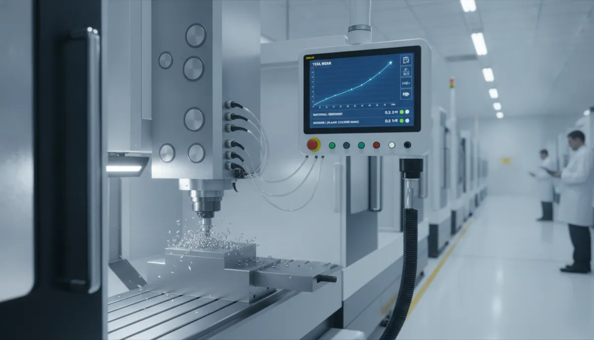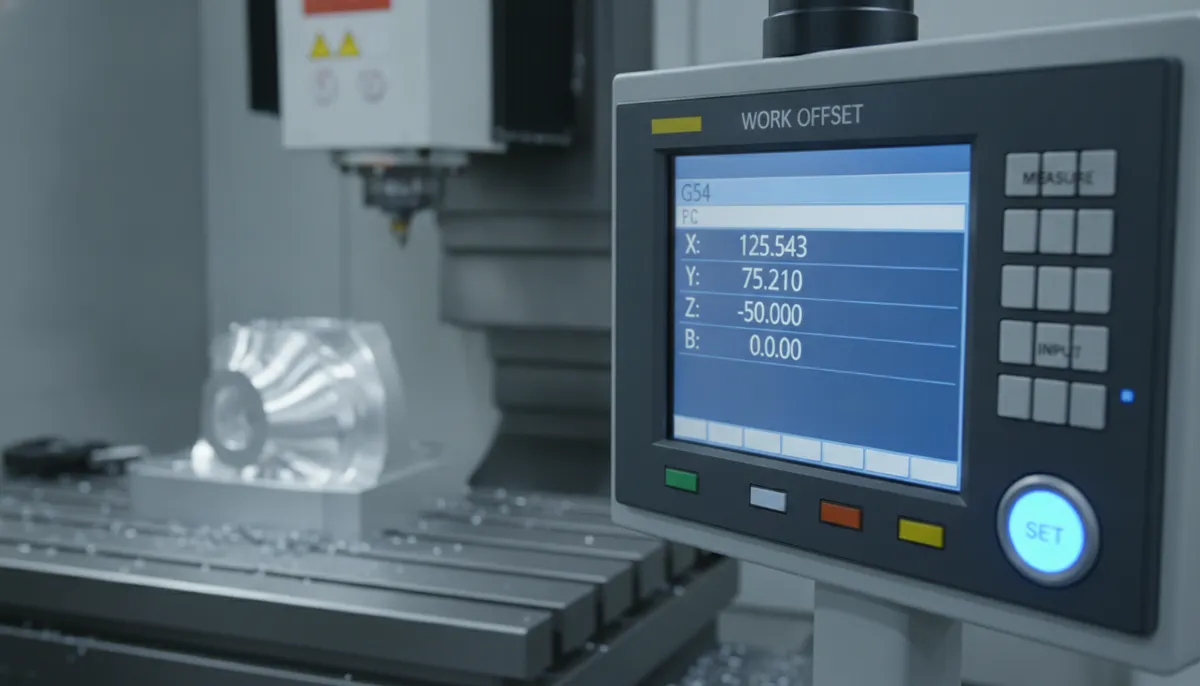
If you’re new to CNC machining, understanding the CNC work coordinate system is one of the most critical skills you need to master. Also known as “fixture offsets” or “part zero,” the CNC work coordinate tells the machine exactly where your part is located on the table — without it, even perfectly written G-code will cut in the wrong place, crash into clamps, or produce scrap. At QiaoFeng CNC, founded in 2010 and trusted by 750+ customers across Europe, North America, and Southeast Asia, we’ve spent 15 years helping machinists master this foundational concept. In this guide, we’ll cover the complete CNC work coordinate definition, explain G54 through G59 in plain language, show you real G-code examples, and walk you through setting part zero step by step.
1. Why CNC Work Coordinates Are More Important Than Ever
The global CNC machining industry is growing at an accelerating pace. According to Mordor Intelligence’s Machining Centers Market Report, the global machining centers market is valued at USD 23.67 billion in 2026 and is projected to reach USD 30.75 billion by 2031 at a CAGR of 5.37%. Meanwhile, Mordor Intelligence’s CNC Market Report places the broader CNC controls market at USD 116.57 billion in 2026, growing steadily through 2031.
As more manufacturers adopt multi-fixture, high-mix production strategies — running multiple part numbers per cycle to maximize machine utilization — the correct setup and management of CNC work coordinates becomes a direct driver of productivity and quality. According to Fortune Business Insights, the global CNC machine tools market was valued at USD 101.22 billion in 2025 and is projected to grow further through 2034 — meaning more machines, more setups, and more operators who need to get work coordinates right the first time.
Setup errors — including incorrect work coordinate offsets — remain one of the most common causes of scrapped parts and machine crashes in job shops worldwide. Mastering G54–G59 is not optional; it is the foundation of reliable CNC production.
2. What Is a CNC Work Coordinate System? (Definition)
A CNC work coordinate system (WCS) defines the origin point of your part — the reference point from which all programmed X, Y, and Z movements are measured. This point is commonly called part zero or program zero. When you write G0 X0 Y0 Z0 in your G-code, the machine moves to this exact point.
It is essential to understand the difference between two coordinate systems that exist simultaneously on every CNC machine:
- Machine Coordinate System (MCS) — The absolute home position of the machine itself, defined by the machine builder. This never changes. It is the machine’s internal reference frame, typically at the far corner of the machine’s travel envelope. You cannot (and should not) change this.
- Work Coordinate System (WCS) — A user-defined offset from the MCS that represents the origin of your specific part. This is what G54, G55, G56, etc. store. You set this for every new job setup.
Think of it this way: the Machine Coordinate System is like the GPS coordinates of a city, fixed and absolute. The Work Coordinate System is like your home address within that city — it shifts depending on where you place your part on the table.
3. G54 Through G59 Explained: The Six Work Offsets
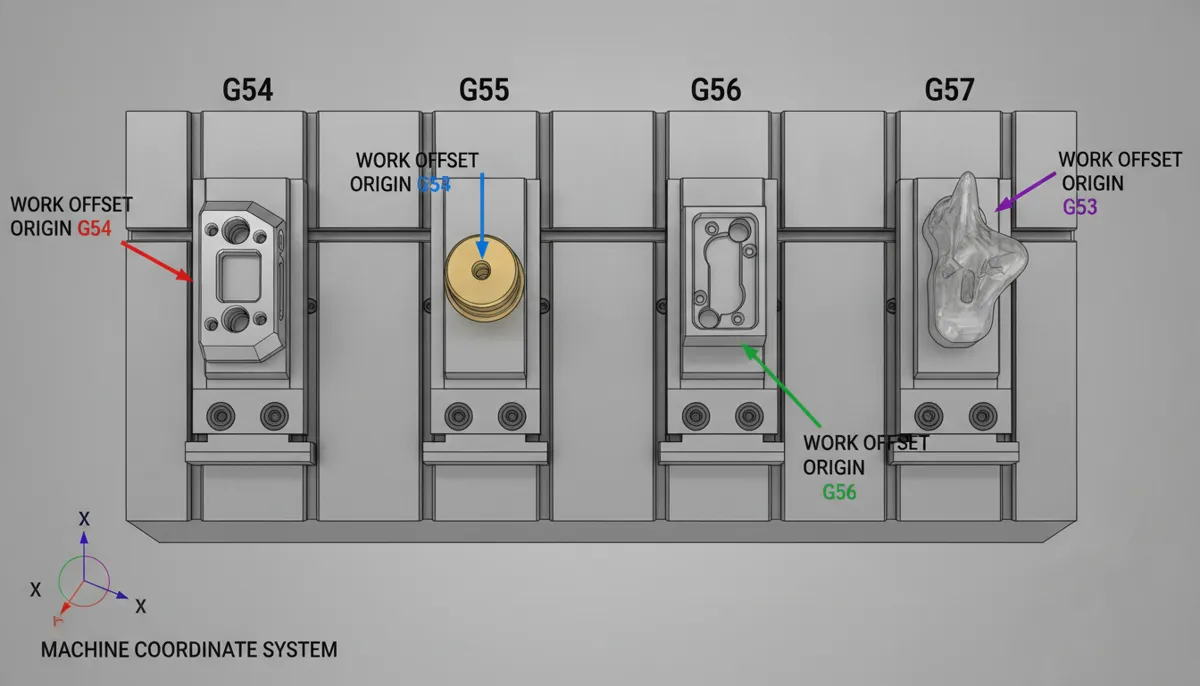
Most CNC controllers (Fanuc, Heidenhain, Siemens, Haas, Mitsubishi) provide at least six standard CNC work coordinate offsets, designated G54 through G59. Each one is an independent memory register that stores a unique XYZ (and optionally ABC rotary) offset value.
| G-Code | Common Name | Typical Use | Notes |
|---|---|---|---|
| G54 | Work Offset 1 | Primary part / Vise 1 | Default offset; most programs start here |
| G55 | Work Offset 2 | Second part / Vise 2 | Used for 2nd fixture or 2nd part position |
| G56 | Work Offset 3 | Third part / Fixture 3 | Multi-part pallets, tombstone setups |
| G57 | Work Offset 4 | Fourth part / Fixture 4 | High-volume production lines |
| G58 | Work Offset 5 | Fifth part / Sub-fixture | Complex jig setups |
| G59 | Work Offset 6 | Safe clearance plane / Home | Often used as a safe Z-retract reference |
| G54.1 P1–P48 | Extended Offsets | Fanuc: up to 48 additional offsets | For pallet changers and high-fixture-count setups |
4. Real G-Code Example: Using CNC Work Coordinates
Here is a practical G-code example showing how CNC work coordinates are called in a real program. This example machines two identical brackets — one at G54, one at G55 — using a subprogram call (M98) to avoid repeating the machining code.
%
O0100 (MAIN PROGRAM - TWO BRACKET SETUP)
G90 G94 G17 G40 G49 G80     (Safety block: absolute, feed/min, XY plane, cancel comp/cycles)
G21                          (Metric mode)
T1 M6                        (Tool change: 10mm End Mill)
G0 G90 G54 X0. Y0. S3000 M3 (Rapid to G54 part zero, spindle ON 3000 RPM)
G43 H1 Z50. M8               (Tool length comp + coolant ON)
M98 P0200                    (Call subprogram for BRACKET 1 at G54)
G0 Z100. M9                  (Retract Z, coolant OFF)

G0 G90 G55 X0. Y0. S3000 M3 (Switch to G55 - BRACKET 2 position)
G43 H1 Z50. M8               (Tool length comp + coolant ON)
M98 P0200                    (Call same subprogram for BRACKET 2 at G55)
G0 Z100. M9                  (Retract Z, coolant OFF)

M5                           (Spindle stop)
G91 G28 Z0.                  (Return Z to home)
G91 G28 X0. Y0.              (Return XY to home)
M30                          (Program end)
%

O0200 (SUBPROGRAM - BRACKET PROFILE)
G0 X10. Y10.                 (Rapid to start position)
G1 Z-5. F500.                (Plunge to depth)
G1 X60. F800.                (Cut along X)
G1 Y50.                      (Cut along Y)
G1 X10.                      (Return along X)
G1 Y10.                      (Return along Y)
G0 Z5.                       (Retract)
M99 (Return to main program)G54 to G55 in the main program, the machine automatically moves to the second part’s origin and runs the identical subprogram. No reprogramming required. This is the power of the CNC work coordinate system in production environments.
5. How to Set a CNC Work Coordinate (Step-by-Step)
Setting a CNC work coordinate correctly is a fundamental skill every machinist must master. Here is the standard procedure for setting G54 on a Fanuc-based machining center:
- Mount your part or fixture securely in the vise or on the table. Ensure it is square and clamped properly.
- Install your edge finder or probe in the spindle. A 10mm mechanical edge finder or a Renishaw touch probe are both common choices.
- Jog to the X-axis part edge. Touch off the left edge of your part. Note the machine X position displayed on the controller (this is the MCS X value). Add or subtract the edge finder radius (e.g., +5mm if using a 10mm edge finder) to get the true part edge in MCS coordinates.
- Jog to the Y-axis part edge. Repeat the same process for the Y axis — touch off the front edge of your part.
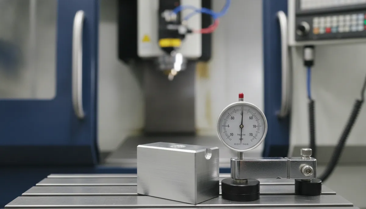
- Set the Z zero. Lower the spindle until the tool tip just touches the top surface of your part (use a paper feeler gauge for precision). This is your Z0 reference.
- Enter the offset values. Navigate to the Work Offset page on your controller (OFFSET → WORK on Fanuc). Enter the MCS X, Y, Z values into the G54 row. Many modern controls have a “Measure” or “Input” button that automatically captures the current machine position.
- Verify the offset. Command
G54 G0 X0 Y0(with spindle off) and visually confirm the tool is positioned exactly at your intended part zero corner. - Dry run before cutting. Run the program at 10% feed rate override with the spindle off to verify all movements before committing to material.
6. Real-World Use Cases for CNC Work Coordinates
6.1 Multiple Parts on One Table
Pain point: You have a large machine table and need to machine 6 identical brackets per cycle. Setting each part’s zero manually takes time and invites human error.
Solution: Use G54 for part 1, G55 for part 2, G56 for part 3, and so on. Each offset stores the exact table location of that part. Once programmed, the machine automatically moves to each part’s CNC work coordinate origin and runs the same subprogram. At QiaoFeng, we’ve seen shops reduce setup time by 40% per shift using this multi-offset strategy.
6.2 Fixture Offsets for Complex Jigs
Pain point: A custom fixture holds a turbine blade at a 15-degree angle. Finding the part zero manually on an angled surface is tedious and error-prone.
Solution: Use G54 for the fixture’s base reference, then G55 for the blade’s machining datum. This separates fixture setup from part programming, simplifies G-code, and ensures full repeatability across production runs. Combining this with a Renishaw probing cycle makes re-zeroing after a part change automatic.
6.3 Safe Z Clearance Plane Using G59
Pain point: After a tool change, the machine needs a guaranteed safe Z height to avoid crashing into tall clamps or fixture risers during rapid traverses.
Solution: Configure G59 with a Z offset set to a high clearance value (e.g., Z+200mm above the table). When the program calls G59 G0 Z0, the machine rapids to this safe clearance height before any repositioning move. This simple technique prevents a large percentage of rapid-traverse crashes in busy production environments.
6.4 Subprograms and High-Volume Repetitive Operations
Pain point: You need to drill a 12-hole pattern on 6 different parts per cycle. Writing 72 individual drilling moves is inefficient and error-prone.
Solution: Write one subprogram (M98) containing the 12-hole pattern, then call it 6 times from the main program — each time activating a different CNC work coordinate offset (G54 through G59). The result is a clean, maintainable program that machines all 6 parts with a single subprogram definition. This technique is standard practice in high-volume automotive and electronics manufacturing.
7. MCS vs. WCS: Key Differences at a Glance
| Aspect | Machine Coordinate System (MCS) | Work Coordinate System (WCS / G54–G59) |
|---|---|---|
| Set by | Machine builder (fixed at factory) | Operator / Setup machinist |
| Changes between jobs? | Never | Yes — reset for every new part setup |
| Reference point | Machine home / reference position | Part zero / program zero |
| Stored in | Machine firmware (non-editable) | Non-volatile controller memory (editable) |
| Survives power loss? | Yes (hardware reference) | Yes (non-volatile memory) |
| Number of systems | 1 per machine | 6 standard (G54–G59); up to 54 with G54.1 |
| Used in G-code? | G53 (direct MCS move) | G54, G55, G56, G57, G58, G59 |
| Typical error risk | Low (set once by builder) | Medium (operator must set correctly each job) |
8. What Our Customers Say About CNC Work Coordinate Setup
“Before we standardized our G54–G59 offset strategy, our setup time for a 6-part pallet was nearly 3 hours. After QiaoFeng’s engineering team helped us implement a structured work coordinate workflow with probing cycles, we cut that to under 45 minutes. The productivity gain was immediate and measurable. Their machines and support are genuinely world-class.”
“We run a mixed production floor machining aerospace brackets and medical housings on the same machines. Managing multiple fixture offsets used to be a source of constant errors. QiaoFeng’s 5-axis machining centers have an intuitive offset management interface, and their team provided us with a complete work coordinate setup guide tailored to our Heidenhain controller. Zero offset-related crashes in 14 months of production.”
“Chúng tôi sản xuất linh kiện điện tử chính xác cho các khách hàng Nhật Bản và Hàn Quốc, yêu cầu dung sai rất chặt chẽ. Hệ thống tọa độ làm việc trên máy phay CNC của QiaoFeng giúp chúng tôi thiết lập G54 đến G57 một cách nhanh chóng và chính xác cho từng ca sản xuất. Kể từ khi sử dụng máy của QiaoFeng, tỷ lệ phế phẩm do lỗi offset đã giảm xuống gần bằng 0.”
9. Pros & Cons: Using Multiple CNC Work Coordinate Offsets
✅ Advantages of Multi-Offset Setup (G54–G59)
- Machine multiple parts per cycle without reprogramming
- Dramatically reduces setup time (up to 40% in production environments)
- Offsets stored in non-volatile memory — survive power loss
- Works seamlessly with subprograms (M98/M99) for clean code
- Supports 4th and 5th axis rotary setups
- Extendable to 54 offsets with G54.1 P1–P48 on Fanuc
❌ Common Pitfalls to Avoid
- Calling wrong offset (e.g., G55 instead of G54) causes positional crash
- Forgetting to update offsets after re-fixturing leads to scrap
- Not verifying offsets before first run is a common beginner mistake
- Old offsets from previous jobs can cause unexpected moves if not cleared
- Rotary axis offsets require careful kinematic understanding on 5-axis machines
10. FAQ: CNC Work Coordinate System Explained
What is the difference between G54 and G55 in CNC machining?
G54 and G55 are both CNC work coordinate offsets, but they store completely independent origin points. Think of them as separate memory slots — G54 might store the zero for part 1 in your left vise, while G55 stores the zero for part 2 in your right vise. You switch between them during a program by simply calling G54 or G55. The machine instantly shifts its reference frame to the new origin. In practice, most Fanuc and Haas machines provide six standard slots (G54–G59), while Fanuc’s extended system (G54.1 P1–P48) provides up to 48 additional offsets for complex pallet setups.
How do I set a CNC work coordinate on my machine?
The standard process is: (1) Mount and square your part. (2) Use an edge finder or touch probe to locate the part edges in X and Y. (3) Touch off the top surface for Z zero. (4) Navigate to the Work Offset page on your controller and enter the measured MCS values into the G54 register. (5) Verify by commanding G54 G0 X0 Y0 with the spindle off and confirming visual alignment. (6) Perform a dry run at reduced feed before cutting. Many modern controllers — including those on QiaoFeng machines — support automatic probing cycles that complete steps 2–4 in under 60 seconds.
Can I use G54–G59 with 4th and 5th axis CNC machines?
Yes. CNC work coordinates apply to all axes, including rotary A, B, and C axes. For 4-axis and 5-axis setups, you typically set the work coordinate origin at the center of rotation of the rotary table or trunnion. This ensures that when the table rotates, the part’s geometry remains accurately referenced to the tool. On 5-axis machines with RTCP (Rotation around Tool Center Point) or TCPM mode, the work coordinate system works in conjunction with the kinematic model to maintain accurate tool positioning throughout complex simultaneous moves. QiaoFeng’s 5-axis machines fully support this workflow on both Heidenhain TNC 640 and Siemens 840D controllers.
What happens if I accidentally call the wrong work offset (e.g., G55 instead of G54)?
The machine will move to a completely different position — wherever G55’s offset values point. If G55 is set to a different part location, the tool may rapid directly into a clamp, fixture riser, or the machine table. This is one of the most common causes of machine crashes in job shops. Prevention strategies include: (1) Always perform a dry run with spindle off before cutting. (2) Use setup sheets that clearly label which offset corresponds to which fixture. (3) Some controllers allow you to name offsets (e.g., “VISE-L” for G54) — use this feature. (4) Implement a pre-run checklist that requires the operator to verify active offset before pressing cycle start.
Do I need to clear CNC work coordinate offsets between jobs?
It is not mandatory, but it is strongly recommended best practice. Leaving stale offsets from a previous job in G54–G59 creates risk — especially if a different operator runs the machine on the next shift without checking. The safest workflow is to: (1) Overwrite all used offsets with new values at the start of each job setup. (2) Zero out any offsets that are not used in the current job. (3) Document all offset values on your setup sheet so they can be quickly re-entered if needed. Some shops also use a “clear offsets” macro that zeros all G54–G59 registers at the start of every shift as a safety reset.
What is G53 and how is it different from G54?
G53 is a special non-modal G-code that commands the machine to move in Machine Coordinate System (MCS) coordinates — bypassing all work offsets entirely. It is typically used to move to a safe tool change position or machine home position that is defined in absolute machine coordinates. Unlike G54–G59, G53 is non-modal (it only applies to the single block it appears in) and does not change the active work offset. After a G53 move, the machine reverts to whichever work offset (G54, G55, etc.) was active before. Use G53 for tool changes and safe retracts; use G54–G59 for all part-relative positioning.
What is QiaoFeng’s warranty and refund policy for CNC machines?
All QiaoFeng CNC machines come with a comprehensive 2-year warranty covering manufacturing defects and quality issues. If a verified quality problem arises, we support full refunds or replacement. We do not offer no-reason returns for correctly functioning machines. Our engineering team provides post-delivery support including work coordinate setup guidance, post processor configuration, and operator training resources. Contact us for full warranty terms.
Ready to Master CNC Work Coordinates on a QiaoFeng Machine?
Get a CNC machining center built for precision, reliability, and ease of setup — backed by 15 years of experience, 750+ global customers, and a 2-year warranty. Free consultation and setup support included for all new customers.
References
- Mordor Intelligence. Machining Centers Market Size, Share & Growth Trends Report, 2026–2031. https://www.mordorintelligence.com/industry-reports/machining-centers-market
- Mordor Intelligence. Computer Numerical Controls (CNC) Market Size & Share Analysis, 2026–2031. https://www.mordorintelligence.com/industry-reports/computer-numerical-controls-market
- Fortune Business Insights. CNC Machine Tools Market Size, Share & Industry Analysis, 2025–2034. https://www.fortunebusinessinsights.com/industry-reports/computer-numerical-controls-cnc-machine-tools-market-101707
- MarketsandMarkets. CNC Machine Market Size, Share and Industry Report, 2023–2028. https://www.marketsandmarkets.com/Market-Reports/cnc-market-195192631.html
- Mountain Home Community College (MHCC). G54–G59: An Introduction to Coordinate Systems — Support for CNC. https://mhcc.pressbooks.pub/supportcnc/chapter/g54-g59-an-introduction/