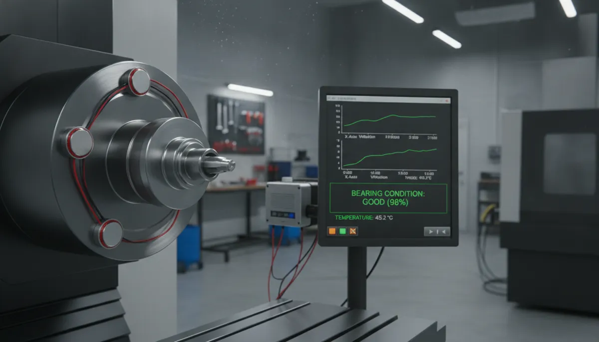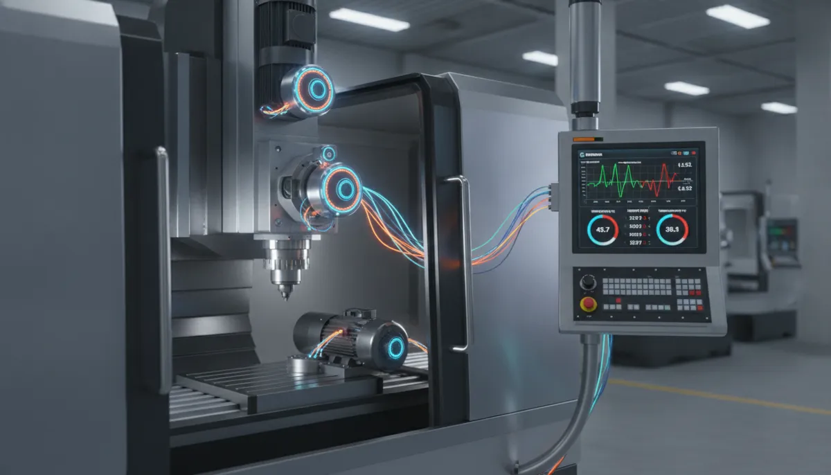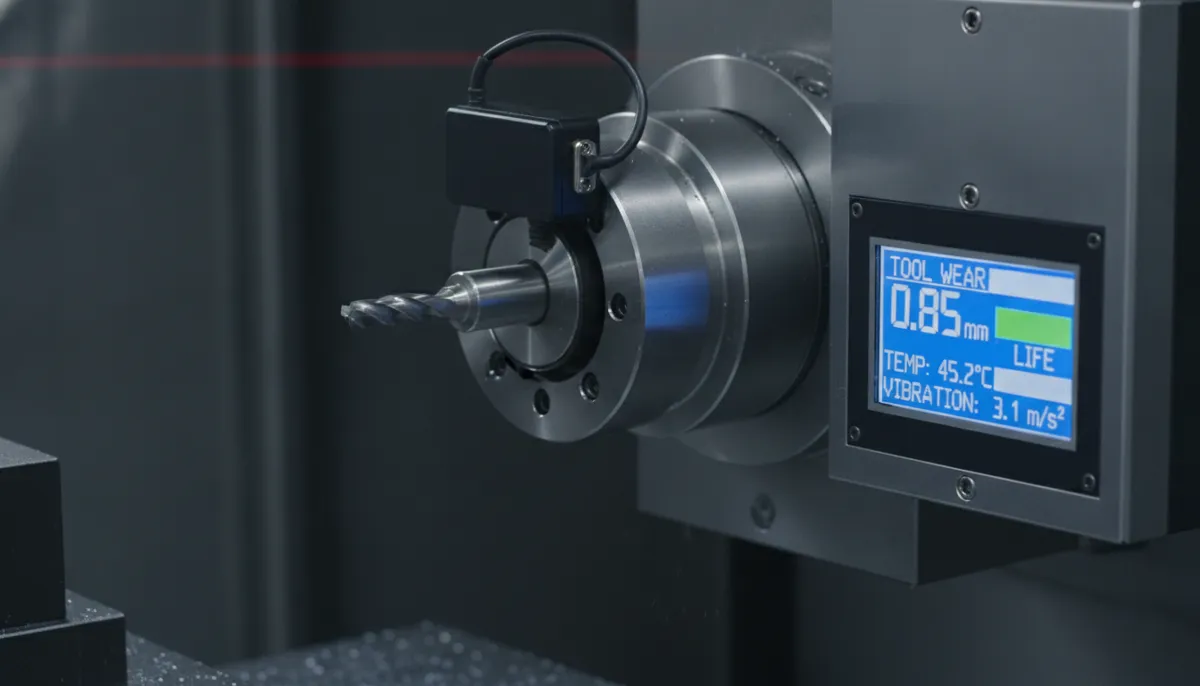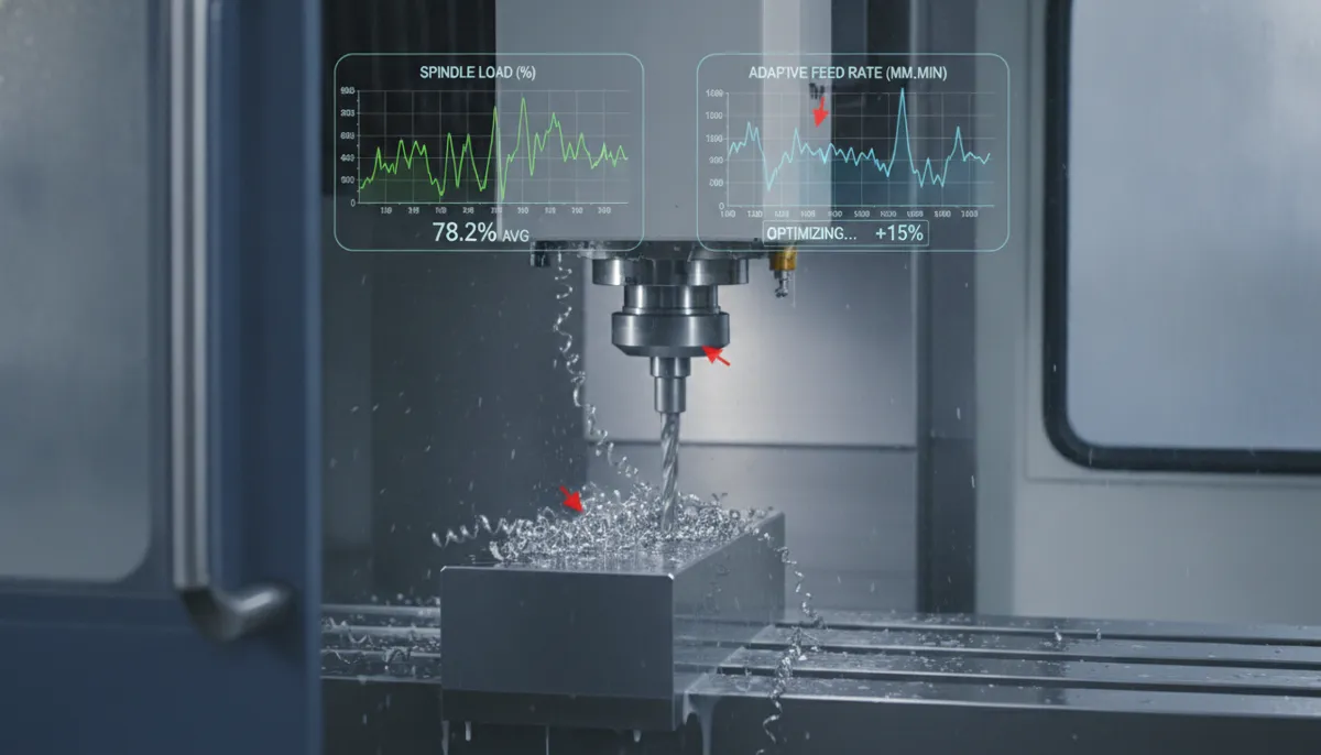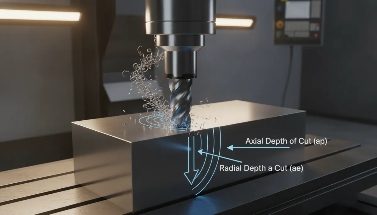
CNC depth of cut is one of the most critical parameters in any machining operation — and one of the most misunderstood by beginners. Whether you’re running a job shop in Germany, a precision parts facility in California, or a growing factory in Vietnam, getting your CNC depth of cut right directly determines your tool life, surface finish, cycle time, and ultimately your profitability. At QFCNCMACHINE.COM, we have been manufacturing and supplying high-precision CNC machine tools since 2010, serving 750+ clients across Europe, North America, and Southeast Asia. In this guide, we break down the CNC depth of cut definition, explain axial depth CNC and radial depth CNC in plain language, and give you actionable parameters you can use today.
1. Why CNC Depth of Cut Matters More Than Ever
The global CNC machines market is projected to reach USD 105.7 billion by 2031, growing at a CAGR of 5.96% from 2026, driven by aerospace re-equipment, electrified-mobility supply chains, and semiconductor capacity expansion (Mordor Intelligence, 2026). Grand View Research similarly estimates the broader CNC market will grow from USD 66.74 billion (2022) to USD 132.93 billion by 2030 (Grand View Research, 2024). As competition intensifies, shops that master fundamental parameters like CNC depth of cut gain a measurable edge.
Peer-reviewed research published in Scientific Reports (Nature, 2024) confirms that depth of cut contributes up to 46.6% of total variability in tool wear and surface roughness — making it the single most impactful cutting parameter to optimize, ahead of cutting speed and feed rate (Elshaer et al., Scientific Reports, 2024). A 2024 study in Frontiers in Mechanical Engineering further demonstrates that systematic optimization of axial cutting depth, feed speed, and tool speed can simultaneously reduce machining time and tool wear while improving surface quality (Wang, Frontiers in Mechanical Engineering, 2024).
2. What Is CNC Depth of Cut? The Complete Definition
CNC depth of cut (DOC) refers to the thickness of material removed from a workpiece in a single machining pass. It is a core input parameter in milling, turning, and drilling operations. There are two distinct types of depth of cut, and confusing them is one of the most common beginner mistakes:
2.1 Axial Depth of Cut (Stepdown)
Axial depth of cut — also called stepdown or axial DOC — is the depth of engagement measured parallel to the spindle axis. In vertical milling, this is how far the end mill plunges downward into the material. It directly controls how much of the tool’s flute length is engaged and has a major influence on cutting forces and deflection.
2.2 Radial Depth of Cut (Stepover)
Radial depth of cut — also called stepover or radial DOC — is the width of cut measured perpendicular to the spindle axis. It defines how much of the tool’s diameter is engaged with the workpiece. In slotting operations, radial DOC equals 100% of tool diameter; in profiling or finishing passes, it is typically 30–70%.
| Parameter | Also Called | Direction | Typical Range (Milling) | Primary Effect |
|---|---|---|---|---|
| Axial DOC | Stepdown, ADOC | Parallel to spindle axis | 0.5×–1.5× tool diameter | Cutting force, deflection, flute engagement |
| Radial DOC | Stepover, RDOC, WOC | Perpendicular to spindle axis | 30%–70% of tool diameter | Chip thinning, heat generation, MRR |
3. Recommended CNC Depth of Cut Parameters by Material
The optimal CNC depth of cut varies significantly by workpiece material, tool type, and machine rigidity. The table below provides a practical starting-point reference based on standard carbide end mills. Always verify against your tool manufacturer’s data sheet and adjust based on spindle load readings.
| Material | Axial DOC (ADOC) | Radial DOC (RDOC) | Notes |
|---|---|---|---|
| Aluminum 6061-T6 | 0.8×–1.5× tool ⌀ | 40%–60% tool ⌀ | High MRR possible; use sharp geometry, flood coolant |
| Mild Steel (1018) | 0.5×–1.0× tool ⌀ | 40%–50% tool ⌀ | Monitor chip color; avoid work hardening |
| Stainless Steel (304) | 0.3×–0.6× tool ⌀ | 30%–40% tool ⌀ | Reduce feed if chatter occurs; use TiAlN coated tools |
| Titanium (Ti-6Al-4V) | 0.2×–0.4× tool ⌀ | 20%–35% tool ⌀ | Low DOC critical; high heat sensitivity — use HSM strategy |
| Hardened Steel (>45 HRC) | 0.1×–0.3× tool ⌀ | 15%–25% tool ⌀ | Use CBN or ceramic inserts; light passes only |
| Plastics / Composites | 1.0×–2.0× tool ⌀ | 50%–80% tool ⌀ | Sharp single-flute preferred; air blast coolant |
Material Removal Rate formula for reference: MRR (in³/min) = ADOC × RDOC × Feed Rate. Increasing either DOC dimension multiplies MRR proportionally — but also multiplies cutting force.
4. Deep vs Shallow Depth of Cut: Pros & Cons
✅ Pros of Deeper DOC
- Higher material removal rate (MRR) — more parts per hour
- Fewer passes needed, reducing program complexity and cycle time
- Better chip thinning effect with high radial engagement
- Lower cost-per-part when machine rigidity allows
- Reduced number of tool changes in long-run production
❌ Cons of Deeper DOC
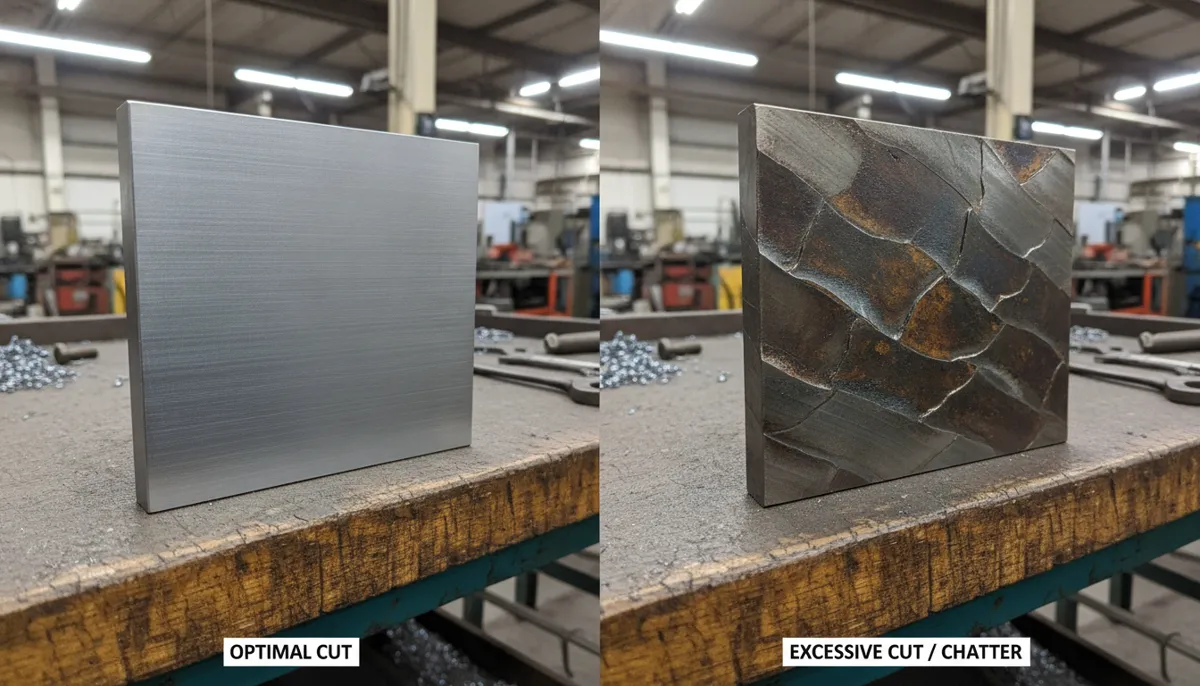
- Higher cutting forces — risk of deflection, chatter, and poor finish
- Increased heat generation, potentially damaging tool coating
- Requires rigid machine, solid workholding, and premium tooling
- Not suitable for thin-wall parts or low-rigidity setups
- Shallow radial DOC (<10% tool ⌀) causes rubbing, not cutting
5. Real-World Case Study: Optimizing DOC for Aluminum 6061-T6
Scenario: A job shop machining aerospace brackets from 6061-T6 aluminum. The programmer used a ½″ 4-flute carbide end mill with a radial DOC of 0.100″ (20% of tool diameter) and axial DOC of 0.200″ (40% of tool diameter). Cycle time per part was 12 minutes, but tool life was only 30 minutes — frequent tool changes were eroding profit margins.
Root Cause: The radial DOC was too small, causing the tool to rub rather than cut cleanly. This generated excessive heat that softened the tool edge coating. The axial DOC was also conservative, requiring too many Z-level passes.
Solution Applied:
- Increased radial DOC from 0.100″ to 0.250″ (50% of tool diameter)
- Increased axial DOC from 0.200″ to 0.400″ (80% of tool diameter)
- Adjusted feed rate to maintain constant chip load per tooth
- Switched to flood coolant to manage heat at higher engagement
Results:
| Metric | Before | After | Improvement |
|---|---|---|---|
| Cycle Time / Part | 12 min | 7 min | ▼ 42% |
| Tool Life | 30 min | 90 min | ▲ 200% |
| Annual Tooling Cost | ~$18,000 | ~$6,000 | ▼ $12,000 saved |
| Surface Finish (Ra) | 1.8 µm | 1.2 µm | ▲ 33% better |
The key insight: chip thinning at higher radial DOC actually reduces the effective chip load per tooth, allowing faster feeds without overloading the tool. This counterintuitive relationship is why DOC optimization requires systematic testing, not guesswork.
6. What Our Clients Say
“We were struggling with inconsistent tool life on our stainless steel components — some tools lasted 20 minutes, others over an hour. Bella and the QFCNCMACHINE team walked us through a proper axial and radial depth of cut setup for our VMC. Within two weeks, our tool life stabilized at 75+ minutes consistently. The difference was night and day. Highly recommend their technical support.”
“As a small job shop in California, we couldn’t afford a full-time process engineer. QFCNCMACHINE’s DOC guidance — especially the radial stepover recommendations for aluminum — helped us cut our cycle times by nearly 35% on aerospace bracket work. Their machines are solid and the after-sales support is genuinely impressive for a factory-direct supplier.”
“เราซื้อเครื่อง VMC จาก QFCNCMACHINE เพื่อผลิตชิ้นส่วนยานยนต์ ทีมงานช่วยเราตั้งค่า depth of cut ที่เหมาะสมสำหรับเหล็กกล้า ทำให้ประสิทธิภาพการผลิตเพิ่มขึ้นอย่างเห็นได้ชัด บริการหลังการขายและการรับประกัน 2 ปีทำให้เรามั่นใจมากในการลงทุนครั้งนี้”
7. Frequently Asked Questions About CNC Depth of Cut
What is the difference between axial and radial depth of cut?
Axial depth of cut (stepdown) is the thickness of material removed along the tool axis — how deep the tool plunges vertically into the workpiece. Radial depth of cut (stepover) is the width of cut perpendicular to the tool axis — how much of the tool’s diameter engages the material sideways. Both affect tool load, chip formation, heat generation, and surface finish. For slotting, radial DOC equals 100% of tool diameter; for profiling, it is typically 30–70%.
How do I calculate the optimal CNC depth of cut for my machine?
Start with your tool manufacturer’s recommended parameters, then factor in your machine’s spindle power, table rigidity, and workholding stiffness. A reliable starting formula for steel: axial DOC = 0.5–1× tool diameter, radial DOC = 40–50% tool diameter. For aluminum, you can typically double those values. Use your machine’s spindle load meter — target 60–80% of rated power. Increase DOC in 10–20% increments while monitoring load and surface finish.
Can too shallow a depth of cut damage my cutting tool?
Yes — this is a frequently overlooked problem. A radial DOC below 10% of tool diameter causes the tool to rub rather than cut, generating excessive frictional heat that softens the tool edge coating and accelerates wear. This is sometimes called “deflection burnishing.” Always maintain a minimum chip thickness of approximately 0.001″ per tooth for carbide tools. If a shallow finish pass is required, use a smaller-diameter tool or increase feed per tooth to ensure proper chip formation.
What depth of cut should I use for 3D surface machining?
For 3D contouring with a ball end mill, use a small axial DOC (0.010″–0.030″) and a moderate radial stepover (10–20% of tool diameter) to control scallop height and achieve smooth surface finish. Larger stepovers increase scallop height and require more polishing time. For roughing passes before 3D finishing, use a larger axial DOC (0.5–1× tool diameter) with a trochoidal or high-efficiency toolpath to maximize MRR while protecting the tool.
Does machine rigidity affect the maximum depth of cut I can use?
Absolutely. Machine rigidity — including spindle bearing preload, guideway type (linear vs. box way), and workholding stiffness — sets the upper limit for practical DOC. A rigid box-way VMC can typically handle 20–30% deeper cuts than a linear-guideway machine at the same spindle power. QFCNCMACHINE’s VMC series uses premium cast iron beds with precision-scraped surfaces to maximize rigidity and allow aggressive DOC settings. Always start conservatively on any new machine and build up parameters through systematic testing.
What is the 2-year warranty coverage on QFCNCMACHINE equipment?
All QFCNCMACHINE CNC machines come with a 2-year warranty covering manufacturing defects and component failures under normal operating conditions. Warranty claims are supported by our technical team with remote diagnostics, spare parts dispatch, and on-site engineer visits where required. Note: warranty applies to quality-related issues; consumable items (tooling, filters, coolant) are not covered. For full warranty terms, please contact us directly.
Ready to Optimize Your CNC Depth of Cut?
Our engineering team (led by Bella, 15 years in CNC manufacturing) offers free cutting parameter consultations for new and existing clients. We serve 750+ manufacturers across Europe, North America, and Southeast Asia — factory direct from Dongguan, China since 2010.
References
- Mordor Intelligence. CNC Machines Market Size, Share & Growth Trends Report, 2026–2031. (2026). https://www.mordorintelligence.com/industry-reports/cnc-machines-market
- Grand View Research. Computer Numerical Control (CNC) Machines Market Size, Share & Trends Analysis Report, 2023–2030. (2024). https://www.grandviewresearch.com/industry-analysis/computer-numerical-controls-cnc-market
- Elshaer, R.N., Abd El-Aty, A., Sayed, E.M., Barakat, A.F., & Sobh, A.S. Optimization of machining parameters for turning operation of heat-treated Ti-6Al-3Mo-2Nb-2Sn-2Zr-1.5Cr alloy by Taguchi method. Scientific Reports, Vol. 14, Article 16494. Nature Publishing Group. (2024). https://www.nature.com/articles/s41598-024-65786-8
- Wang, Z. The milling parameters of mechanical parts are optimized by NC machining technology. Frontiers in Mechanical Engineering, Vol. 10. (2024). https://doi.org/10.3389/fmech.2024.1367009