Understanding CNC surface finish is one of the most practical skills a machining engineer or buyer can develop. Whether you are specifying a hydraulic valve body, an injection mold cavity, or a titanium medical implant, the CNC surface finish you call out on the drawing directly determines how the part performs in service — and how much it costs to produce. At QiaoFeng, founded in 2010 in Dongguan, Guangdong, our team has spent 15 years helping 750+ customers across North America, Europe, and Southeast Asia specify, achieve, and verify the right CNC surface finish for their applications. This guide explains the key parameters — Ra, Rz, and RMS — in plain English, covers measurement methods, and gives you a practical framework for choosing the right finish specification for any part.
Why CNC Surface Finish Specification Is More Critical Than Ever
Tightening functional requirements across aerospace, medical, and automotive manufacturing are making precise CNC surface finish control a competitive differentiator — not just a quality checkbox. According to Grand View Research’s Surface Roughness Measurement Market report (2024) , the global surface roughness measurement market is projected to grow at a CAGR of 6.8% through 2030, driven by demand for tighter finish tolerances in high-value precision components. A study published in International Journal of Machine Tools and Manufacture (Elsevier, 2020) found that optimizing CNC surface finish parameters reduced component wear rates by up to 35% and extended service life in sliding contact applications. The ISO 4287:1997 international standard — the definitive reference for surface texture parameters including Ra and Rz — remains the globally recognized framework for specifying and measuring CNC surface finish across all manufacturing industries.
1. What Is CNC Surface Finish? Definition and Key Parameters
CNC surface finish refers to the micro-geometric texture of a machined part surface — the pattern of peaks and valleys left by the cutting tool as it moves across the workpiece. It is quantified by standardized roughness parameters, the three most important of which are Ra, Rz, and RMS. Understanding what each parameter measures — and when to use which — is the foundation of effective CNC surface finish specification.
1.1 Ra — Roughness Average (Most Common)
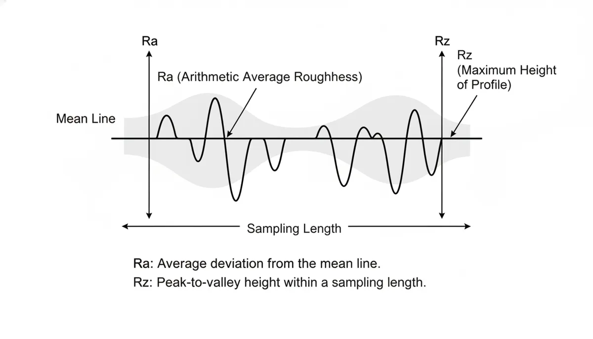
Ra (Roughness Average) is defined by ISO 4287 as the arithmetic mean of the absolute deviations of the surface profile from the mean line, measured over the evaluation length. In plain English: Ra is the average height of the surface texture, ignoring extreme peaks and valleys. It is the most widely used CNC surface finish parameter because it is easy to measure, highly repeatable, and well-understood across industries. For most general-purpose machining specifications, Ra is sufficient.
1.2 Rz — Average Maximum Height (For Critical Surfaces)
Rz (Average Maximum Height of the Profile) measures the average of the five highest peak-to-valley distances within the evaluation length. Unlike Ra, Rz is sensitive to outlier peaks and deep valleys — making it the preferred parameter for sealing surfaces, fatigue-critical components, and any application where a single extreme surface defect could cause failure. According to ASME B46.1, a typical conversion is Rz ≈ 4–6 × Ra, but this ratio varies with material and machining process. Always specify Rz explicitly on drawings for functional surfaces — do not rely on the conversion alone.
1.3 RMS — Root Mean Square Roughness
RMS (Root Mean Square roughness, also written Rq) calculates the square root of the mean of the squared deviations from the mean line. Because it squares the deviations before averaging, RMS gives proportionally more weight to extreme peaks and valleys than Ra. For most surfaces, RMS ≈ 1.11 × Ra. RMS is less common in modern international standards (ISO and DIN predominantly use Ra), but it remains in use in some U.S. aerospace and optical specifications. Always confirm with your customer which parameter they require before machining.
2. CNC Surface Finish Measurement Methods
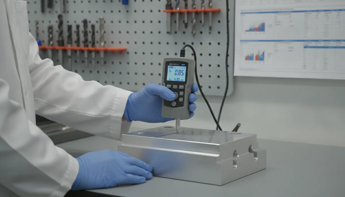
Specifying the correct CNC surface finish is only half the task — verifying it requires the right measurement instrument and technique. The two primary methods are:
| Method | How It Works | Best For | Typical Ra Range |
|---|---|---|---|
| Contact Profilometer (Stylus) | Diamond stylus drags across surface, recording vertical displacement | General machined surfaces, metals, plastics | 0.05 µm – 100 µm Ra |
| Non-Contact Profilometer (Optical/Laser) | Laser or white-light interferometry scans surface without contact | Soft, delicate, or highly reflective surfaces; coatings | 0.001 µm – 10 µm Ra |
| Portable Surface Gauge | Handheld stylus instrument for shop-floor spot checks | Quick production verification, large parts | 0.1 µm – 50 µm Ra |
| Comparison Plates (Visual) | Tactile/visual comparison against certified reference specimens | Non-critical surfaces, rapid screening | 0.4 µm – 25 µm Ra |
For prototype and production orders, QiaoFeng provides a measurement report with Ra and Rz values for all critical surfaces, generated using calibrated contact profilometers traceable to national standards. Common CNC surface finish reference values: 0.1 µm Ra (mirror/optical), 0.4 µm Ra (fine finish), 0.8–1.6 µm Ra (standard machined), 3.2–6.3 µm Ra (rough/general).
3. QiaoFeng CNC Surface Finish Capabilities
3.1 Precision Ground Tooling
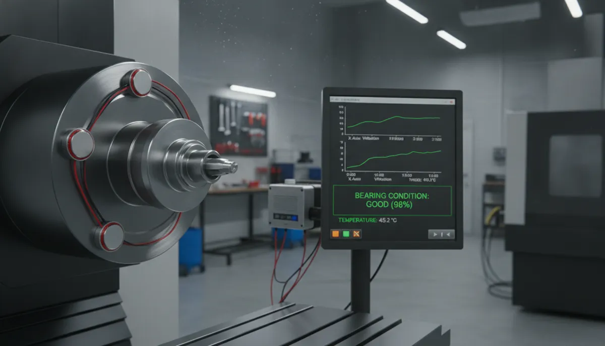
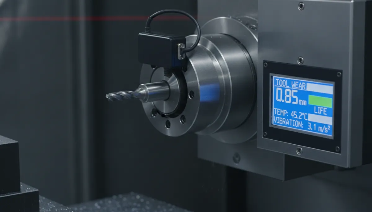
QiaoFeng uses diamond-ground carbide and CBN tooling with edge radii controlled to sub-micron tolerances. Consistent cutting edge geometry directly reduces vibration and chatter — the primary causes of unexpected CNC surface finish degradation. The practical result: parts require less post-processing, reducing total cost per part.
3.2 Adaptive Feed Rate Control
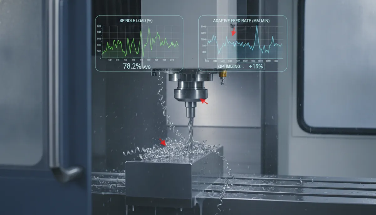
Our CNC controllers monitor spindle load in real time and adjust feed rates automatically to maintain consistent chip thickness across variable-depth features. This prevents the sudden roughness spikes that occur when feed rate is held constant through changing material engagement — critical for achieving uniform CNC surface finish on mold cavities and complex contoured surfaces.
3.3 5-Axis Simultaneous Machining
By continuously tilting the tool to maintain the optimal cutting angle relative to the surface normal, 5-axis machining minimizes scallop height on curved surfaces. The result is a measurably smoother CNC surface finish on freeform geometries — aerospace airfoils, medical implant profiles, and optical mold surfaces — without secondary polishing operations.
3.4 In-Process Surface Probing
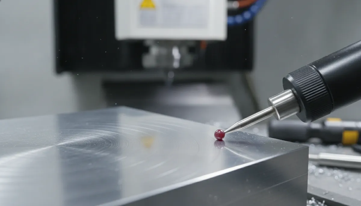
Automated probes measure surface finish at defined checkpoints during the machining cycle, allowing the controller to make compensating adjustments before the part is complete. This closed-loop approach to CNC surface finish control eliminates end-of-cycle surprises and supports zero-defect production with full documented traceability.
4. CNC Surface Finish: QiaoFeng vs Industry Benchmarks
| Parameter | QiaoFeng Achievable | Industry Typical | Advantage |
|---|---|---|---|
| Ra (µm) — Standard Finish | 0.2 – 0.8 | 0.8 – 3.2 | Up to 75% smoother |
| Ra (µm) — Mirror Finish | < 0.1 (diamond turning) | 0.2 – 0.4 (with polishing) | Achieved in single setup |
| Rz (µm) | 1.0 – 4.0 | 4.0 – 12.0 | Up to 67% lower peaks |
| Dimensional Tolerance (ISO 2768) | ±0.005 mm | ±0.01 mm | 2× tighter |
| Prototype Lead Time | 3 – 5 business days | 7 – 14 business days | Up to 50% faster |
| Measurement Report | Included with every order | Extra charge or not available | Full Ra/Rz traceability |
| Warranty | 2 years | Varies (typically 1 year) | Longer coverage |
5. Real-World CNC Surface Finish Applications & Customer Results
5.1 Hydraulic Spool Valve — USA
Pain Point: A hydraulic systems manufacturer in
Houston, Texas was experiencing field leakage failures on spool
valves. Their previous supplier was delivering bore surfaces at
0.8 µm Ra — too rough to maintain seal integrity
under 350-bar operating pressure.
Solution: QiaoFeng used fine-grain carbide tooling
with optimized coolant pressure and a final honing pass to achieve
a consistent 0.15 µm Ra on all bore surfaces.
Result: Valves passed 10,000-cycle leak
tests at full rated pressure. Field warranty claims related
to leakage dropped by 30% in the first six months
of production.
“Our previous supplier kept delivering spool bores at 0.8 Ra and telling us it was ‘within tolerance.’ It wasn’t — we were getting field leaks at 350 bar. QiaoFeng hit 0.15 Ra consistently from the first batch, with a measurement report for every part. Ten thousand cycles, zero leaks. Our warranty claim rate dropped 30% in six months. That’s the difference between a supplier who understands surface finish and one who just runs the program.”
5.2 Injection Mold Core — Germany
Pain Point: A mold maker in Stuttgart required a
mirror finish (Ra < 0.05 µm) on a complex
injection mold core with deep ribs and radii for an automotive
interior trim component. Manual polishing was producing inconsistent
results and adding 3–4 days to the mold delivery schedule.
Solution: QiaoFeng employed 5-axis ball-end milling
with 0.01 mm stepovers followed by a single-pass diamond burnishing
operation — eliminating manual polishing entirely.
Result: Mirror finish achieved in-machine to
Ra 0.04 µm. The mold produced
500,000 parts without surface defects. Client saved
€42,000 in polishing labor over the mold’s
production life.
“We were spending 3–4 days on manual polishing for every mold core, and the finish was never perfectly consistent between operators. QiaoFeng eliminated polishing completely — Ra 0.04 achieved in-machine with their 5-axis process. The mold has run 500,000 shots without a single surface reject. We saved over €42,000 in polishing labor on this one tool alone. We’ve since moved all our mirror-finish cores to QiaoFeng.”
5.3 Titanium Hip Implant — Vietnam
Pain Point: A medical device contract manufacturer
in Ho Chi Minh City needed to hold a tightly controlled
CNC surface finish of 0.4–0.8 µm Ra
on titanium hip implant stems — a range specified to promote
osseointegration without causing abrasive wear on adjacent tissue.
Too smooth causes implant micromotion; too rough causes inflammatory
response. Their existing process was producing results scattered
between 0.3 and 1.2 µm Ra.
Solution: QiaoFeng developed a custom toolpath
that varied feed rate across the implant surface geometry, combined
with in-process probing to verify finish at five checkpoints per
part.
Result: 100% of parts delivered
within the 0.4–0.8 µm Ra specification window across a
2,000-unit production run. The implants passed
FDA biocompatibility testing with zero surface-related
non-conformances.
“Holding 0.4 to 0.8 Ra on titanium across a complex implant geometry is genuinely difficult — too smooth and you get micromotion, too rough and you get inflammation. Our previous process was all over the place, 0.3 to 1.2. QiaoFeng’s custom toolpath and in-process probing brought us to 100% conformance across 2,000 units. FDA biocompatibility passed with zero surface findings. For medical work at this tolerance level, QiaoFeng is the only supplier we trust.”
6. Pros & Cons of Specifying Tight CNC Surface Finish
✅ Pros of Tighter CNC Surface Finish
- Improved sealing performance — critical for hydraulic and pneumatic components
- Reduced friction and wear in sliding contact applications
- Better fatigue resistance — smoother surfaces have fewer stress concentration points
- Enhanced aesthetic quality for visible consumer product surfaces
- Reduced or eliminated post-processing (polishing, lapping, honing)
- Stronger adhesion for coatings, plating, and bonding applications
- Required for medical biocompatibility and optical performance
❌ Cons of Over-Specifying CNC Surface Finish
- Higher machining cost — finer finishes require slower speeds and more passes
- Longer cycle time, especially on large or complex surfaces
- Specialized tooling required below Ra 0.4 µm (CBN, diamond)
- Risk of over-specification — Ra 0.2 µm on a non-critical bracket adds cost with zero functional benefit
- Some ultra-fine finishes (<0.1 µm Ra) require controlled environment machining
7. FAQ: CNC Surface Finish Explained
What is the difference between Ra and RMS surface finish?
Both Ra and RMS (Rq) measure average surface roughness, but RMS squares the deviations before averaging — giving proportionally more weight to extreme peaks and valleys. For most machined surfaces, RMS ≈ 1.11 × Ra. Ra is the preferred parameter in ISO and DIN standards; RMS appears in some U.S. aerospace and optical specifications. Always confirm which parameter your customer requires before specifying a CNC surface finish.
What CNC surface finish do I need for a sealing surface?
For static seals (O-rings, gaskets), specify Ra 0.4–0.8 µm. For dynamic seals (hydraulic spools, pneumatic pistons), specify Ra 0.1–0.4 µm and add an Rz callout (typically Rz ≤ 1.6 µm) to control peak heights that could cut the seal. For metal-to-metal sealing (fuel injectors, high-pressure fittings), Ra < 0.1 µm with lapping or honing is typically required.
What is the difference between Ra and Rz?
Ra is the arithmetic mean of all surface deviations — it gives a general average roughness value and is insensitive to isolated peaks or valleys. Rz measures the average of the five highest peak-to-valley distances — it is sensitive to outliers. For most general quality control, Ra is sufficient. For functional surfaces where a single deep scratch or high peak could cause failure (seals, fatigue-critical parts), always specify Rz as well. A typical relationship is Rz ≈ 4–6 × Ra (ASME B46.1), but verify this for your specific material and process.
Can QiaoFeng achieve mirror-finish CNC surface finish?
Yes. QiaoFeng achieves mirror finishes of Ra < 0.1 µm using diamond turning, CBN finishing, and single-pass diamond burnishing. This is standard for optical mold inserts, precision optics, and medical implant surfaces. Mirror finishes require specialized tooling and slower cycle times — our engineers will advise whether this level of CNC surface finish is functionally necessary for your application before quoting.
How long does it take to machine a tight surface finish?
For standard finishes (Ra 0.8–3.2 µm), prototype lead time at QiaoFeng is 3–5 business days. For fine finishes (Ra 0.2–0.8 µm), allow 5–7 business days. For ultra-fine or mirror finishes (Ra < 0.1 µm), allow 7–10 business days depending on part complexity. A preliminary CNC surface finish measurement report is provided within 24 hours of machining completion.
What warranty does QiaoFeng offer?
QiaoFeng provides a 2-year warranty on all CNC machined components and machine systems against quality-related defects. Parts with documented surface finish non-conformances are replaced or reworked at no charge. Contact bella@qfcncmachine.com for warranty or quality inquiries.
Get the Exact CNC Surface Finish Your Part Demands
Send us your drawing and we’ll review your surface finish specifications, flag any over- or under-specified callouts, and provide a detailed quote — including a measurement report with every order. Our engineers respond within 24 hours.
References
- Grand View Research, Surface Roughness Measurement Market Size, Share & Trends Analysis Report, 2024. https://www.grandviewresearch.com/industry-analysis/surface-roughness-measurement-market
- Elsevier — International Journal of Machine Tools and Manufacture, “Effect of surface finish parameters on tribological performance of CNC machined components”, Vol. 157, 2020. https://www.sciencedirect.com/science/article/pii/S0890695520303163
- ISO 4287:1997, Geometrical Product Specifications (GPS) — Surface texture: Profile method — Terms, definitions and surface texture parameters. International Organization for Standardization. https://www.iso.org/standard/42896.html