A CNC way cover alarm is a safety-triggered fault that stops your lathe mid-cycle the moment the controller detects the way cover is out of position — costing you production time and, if left unresolved, risking serious damage to your linear guides and ball screws. At QFCNCMACHINE, founded in 2010 and based in Dongguan, Guangdong, China, our team has helped 750+ machine shops across Europe, the Americas, and Southeast Asia diagnose and eliminate way cover faults. With 15 years of CNC field experience, this guide covers every common cause of a CNC way cover alarm — from misaligned limit switches to chip-jammed tracks — and gives you a clear, step-by-step path to resolution.
1. Why CNC Way Cover Alarms Are a Serious Production Risk
The global CNC machine tools market was valued at USD 66.74 billion in 2022 and is projected to reach USD 132.93 billion by 2030, growing at a CAGR of 9.0%.[1] As production volumes and machine utilisation rates climb, unplanned downtime caused by peripheral faults — including way cover alarms — becomes increasingly costly. The machining centers segment alone is forecast to grow from USD 36.4 billion in 2023 to USD 56.8 billion by 2029, reflecting the industry’s dependence on reliable, continuously operating equipment.[2]
Way cover systems are a critical but often overlooked maintenance area. Industry maintenance engineering analysis identifies cover track obstruction, limit switch misalignment, and interlock wiring faults as the three leading causes of way cover alarms on CNC turning centers — all of which are preventable with structured inspection routines.[3] Left unaddressed, a stuck or misaligned way cover allows coolant and chips to infiltrate the guideways, accelerating linear guide and ball screw wear and leading to accuracy loss that requires far more costly repairs.
2. Understanding the CNC Way Cover Alarm
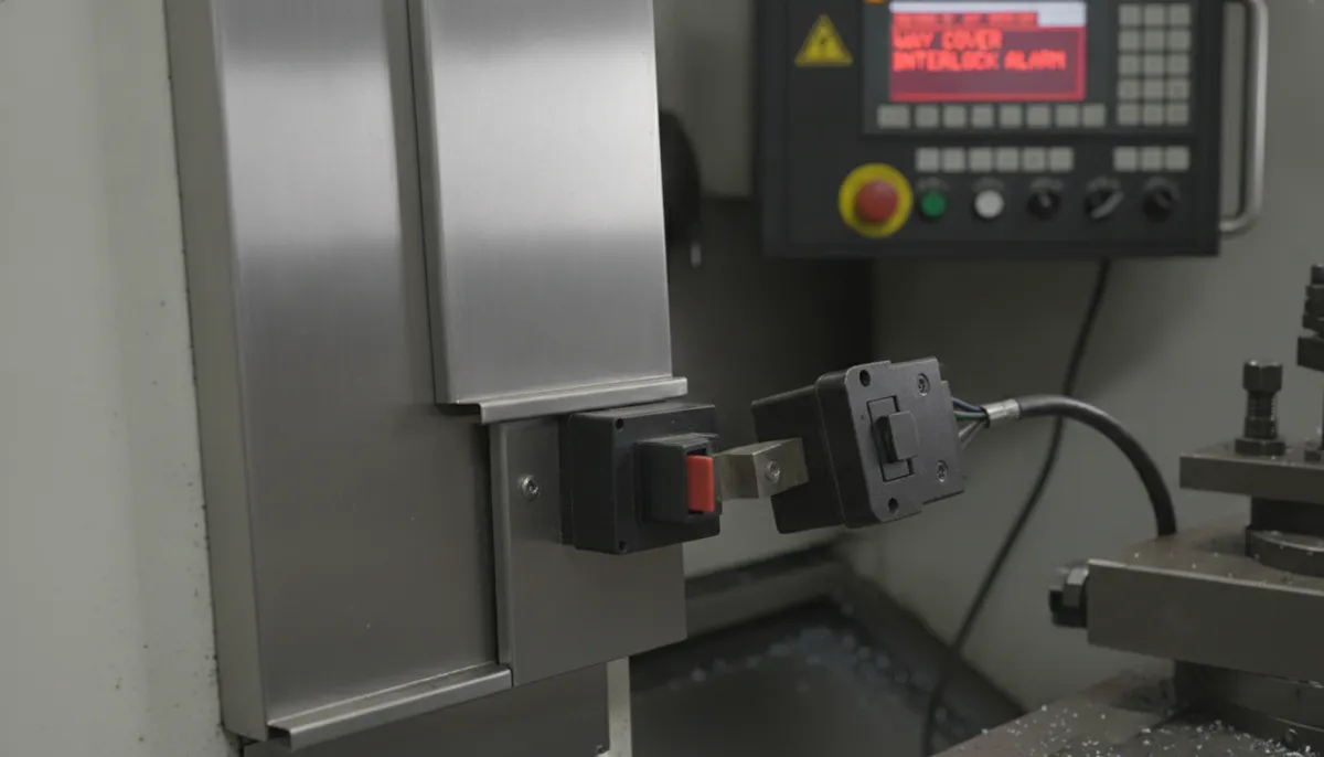
The CNC way cover alarm is a built-in safety feature of your machine’s control system. When the controller detects that the way cover has not reached its expected position — or has moved out of position during a cycle — it triggers an alarm and halts axis motion to prevent mechanical damage. The fault is almost always linked to one of three subsystems: the cover limit switch, the CNC way cover interlock circuit, or the physical cover and track mechanism itself.
Common CNC Way Cover Alarm Triggers
- Misaligned or dirty limit switch: The most frequent cause. The switch that confirms cover position drifts out of range or its face becomes coated with coolant and swarf, producing a false “open” signal.
- Chip or debris obstruction in the track: Heavy chip loads — especially from stainless steel, cast iron, or large-diameter parts — pack into the cover track and prevent full closure, triggering the position sensor.
- Interlock wiring fault: Coolant ingress, vibration-induced connector loosening, or cable chafing can break the interlock circuit and generate a CNC way cover alarm even when the cover is physically in position.
- Bent or deformed cover section: Impact from a workpiece or tooling crash can deform a cover panel, preventing smooth travel and causing intermittent alarms.
- Controller parameter error: Incorrect dwell time or position tolerance settings in the CNC parameters can cause the controller to flag a fault before the cover has had time to complete its travel.
3. CNC Way Cover Alarm Quick-Reference Diagnostic Table
| Symptom | Most Likely Cause | First Check | Typical Fix |
|---|---|---|---|
| Alarm triggers at same axis position every cycle | Debris packed in track at that point | Visual inspection of track at alarm position | Clear debris; install brush seal or chip guard |
| Alarm triggers intermittently, no pattern | Loose limit switch connector or cable chafe | Wiggle test on limit switch cable; multimeter continuity check | Secure connector; replace damaged cable section |
| Alarm triggers after coolant flood | Coolant ingress on limit switch or interlock connector | Inspect switch housing and connector for moisture | Dry and reseal; replace switch with IP67-rated unit |
| Cover moves but alarm persists | Limit switch gap out of specification | Measure switch-to-target gap with feeler gauge | Re-adjust gap to manufacturer spec (typically 1–3 mm) |
| Cover does not travel fully — mechanical stop | Bent cover panel or deformed track | Manual travel test; check for binding or resistance | Straighten or replace deformed cover section; realign track |
| Alarm only on thermal warm-up | Thermal expansion shifting interlock bracket | Check bracket position cold vs. warm | Install adjustable bracket with thermal compensation slot |
4. Step-by-Step CNC Way Cover Alarm Troubleshooting Checklist
Work through these five steps in order before replacing any components. This sequence resolves the majority of CNC way cover alarm faults without parts cost.
- Step 1 — Record the Exact Alarm Code and Axis: Note the full alarm code, sub-code, and which axis was in motion when the fault triggered. This tells you which cover section and which limit switch to inspect first.
- Step 2 — Visual Inspection of Cover and Track: With the machine in E-stop, manually slide the cover through its full travel range. Feel for binding, listen for scraping, and look for chip accumulation, bent panels, or displaced track sections.
- Step 3 — Clean the Track and Cover Faces: Remove all chips, swarf, and coolant residue from the track channel and cover overlap joints. Many CNC way cover alarm events are resolved at this step alone — particularly on machines running cast iron or stainless steel.
- Step 4 — Inspect and Test the Limit Switch: Locate the limit switch that monitors cover position. Clean the switch face. Use a multimeter to verify output signal when the cover is in the closed position. Measure the gap between switch and target — adjust to the manufacturer’s specification if out of range.
- Step 5 — Check Interlock Wiring and Connectors: Inspect the interlock circuit cable from the switch back to the control cabinet. Look for chafing, pinching, or loose connectors. Perform a continuity test. Reseat all connectors and apply strain relief where the cable is subject to movement.
5. Key Features of a Reliable CNC Way Cover System
5.1 Precision Limit Switch Alignment
High-precision limit switches factory-calibrated to tight position tolerances are the single most effective way to reduce false CNC way cover alarms. Switches with IP67 ingress protection ratings resist coolant contamination — the leading cause of premature switch failure on turning centers. When replacing a faulty switch, always verify the replacement carries the same operating voltage and output type (NPN/PNP) as the original to avoid controller compatibility issues.
5.2 Robust Interlock Mechanism
The CNC way cover interlock is a mandatory safety circuit — it prevents axis motion when the cover is not confirmed closed. Designs using sealed contacts and self-cleaning track geometry significantly outperform standard open-contact interlocks in high-coolant, high-chip environments. Never bypass or disable the interlock circuit; doing so removes a critical layer of machine and operator protection and will void your machine warranty.
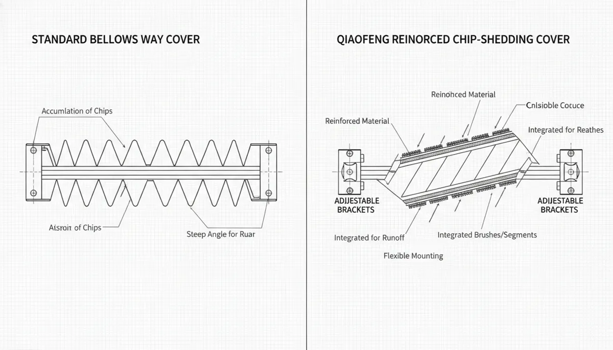
5.3 Chip-Shedding Cover Design
For heavy-duty operations — large-diameter turning, interrupted cuts, or materials with high chip volume such as cast iron and stainless steel — cover geometry matters. Covers with angled overlap joints, integrated brush seals at the track entry, and high-torque drive mechanisms shed chips before they can pack into the track and trigger a CNC way cover alarm. Retrofitting a chip guard at the track entry point is a low-cost upgrade that dramatically reduces alarm frequency in high-chip environments.
5.4 Thermal Compensation Brackets
In shops running continuous multi-shift operations, thermal expansion of the machine structure can shift the interlock bracket by 0.5–2 mm over a warm-up cycle — enough to move the limit switch target out of the detection zone and trigger a CNC way cover alarm that disappears once the machine reaches thermal equilibrium. Adjustable brackets with slotted mounting holes allow the switch position to be set at operating temperature, eliminating this class of fault entirely.
6. Real-World CNC Way Cover Alarm Case Studies
Case 1 — Aerospace Turning Center, Frankfurt, Germany
A precision aerospace components manufacturer in Frankfurt operating a fleet of turning centers experienced frequent CNC way cover alarms on their Z-axis covers during high-volume titanium and aluminium alloy runs. The alarm was triggered by coolant pressure building up inside the cover overlap joints, forcing the cover off its track and activating the position sensor. The solution involved installing reinforced covers with pressure-equalising vents and replacing the standard limit switches with IP67-rated sealed units. Alarm frequency dropped substantially, and the covers have operated without fault through multiple production quarters.
“We were stopping the line multiple times per shift for way cover alarms — it was costing us hours every week. After switching to sealed limit switches and adding the pressure vents, the alarms stopped completely. QFCNCMACHINE’s technical guidance was detailed and practical. Our engineers implemented the fix in one afternoon.”
Case 2 — Stainless Steel Job Shop, Ontario, Canada
A mid-size job shop in Ontario running short-batch stainless steel and Inconel components experienced recurring CNC way cover alarm faults after every tool change cycle. Investigation revealed the interlock bracket was shifting due to thermal expansion during warm-up, moving the limit switch target just outside the detection window. Installing adjustable brackets with thermal compensation slots and resetting the switch gap at operating temperature resolved the issue. The shop reported zero way cover alarms across a full production month following the fix, with throughput improving noticeably.
“The alarm only happened in the first hour of the shift, then disappeared — we thought it was a ghost fault. Bella’s team identified the thermal expansion issue immediately. The bracket adjustment took 30 minutes and we haven’t seen the alarm since. Simple fix, big impact on our morning productivity.”
Case 3 — Heavy-Duty Oilfield Parts Manufacturer, Rayong, Thailand
A manufacturer of large-diameter oilfield valve components in Rayong, Thailand, experienced CNC way cover alarm events whenever machining parts over 300 mm diameter — heavy chip loads from the roughing passes were packing into the cover track and preventing full closure. QFCNCMACHINE recommended retrofitting chip-shedding covers with integrated brush seals at the track entry and a high-torque drive mechanism. The retrofit was completed during a scheduled maintenance window. Alarm events were eliminated, cover service life extended significantly, and the maintenance team reported a measurable reduction in guideway cleaning frequency.
“Large parts mean large chips, and our covers were jamming constantly. We tried cleaning more often but it was not enough. The brush seal retrofit from QFCNCMACHINE solved the root cause — chips no longer reach the track. Our operators are very happy and maintenance time is much less now.”
7. DIY Fix vs. Professional Service for CNC Way Cover Alarms
✅ Operator Can Fix — These Cases
- Chip or debris obstruction in the cover track
- Limit switch gap out of specification — re-adjustment only
- Loose connector or cable not seated properly
- Coolant on switch face — clean and dry
- Controller parameter dwell time too short — software adjustment
- Alarm is intermittent and linked to thermal warm-up
⚠️ Call a Professional — These Cases
- Bent or cracked cover panel requiring replacement
- Track deformation from a crash — alignment required
- Interlock circuit fault traced to control cabinet wiring
- Drive mechanism failure (motor, belt, or actuator)
- Machine under warranty — DIY may void coverage
- Alarm persists after completing all five checklist steps
8. FAQ — CNC Way Cover Alarm Troubleshooting
Q1: What causes a CNC way cover alarm?
The alarm is triggered when the machine’s controller does not receive confirmation that the way cover has reached its expected closed position. The most common causes are a misaligned or contaminated limit switch, chip or debris obstruction in the cover track, a loose interlock connector, or a bent cover panel preventing full travel. In rare cases, a controller parameter error — such as an insufficient position dwell time — can cause the alarm even when the cover is physically correct.
Q2: How do I reset a CNC way cover alarm?
First, identify and resolve the root cause — do not simply reset the alarm without diagnosing the fault. Clear any debris from the track, verify the cover travels freely through its full range, and confirm the limit switch is clean and correctly gapped. Once the physical cause is resolved, manually cycle the cover to its home position using the machine’s jog or MDI mode, then reset the alarm via the controller’s alarm reset function. If the CNC way cover alarm returns immediately, the root cause has not been fully resolved.
Q3: Is the CNC way cover interlock necessary — can I bypass it?
No. The interlock is a mandatory safety circuit that prevents axis motion when the cover is not confirmed closed. Bypassing it exposes operators to injury risk from moving axes and removes protection against coolant and chip ingress into the guideway system. Bypassing the interlock will also void your machine warranty. Always maintain and repair the interlock — never disable it.
Q4: Can a way cover fault cause other machine problems?
Yes — and this is why prompt resolution matters. A stuck or misaligned cover allows chips and coolant to reach the linear guides and ball screws directly. Over time this causes accelerated wear, loss of positioning accuracy, and ultimately requires expensive guideway or ball screw replacement. A CNC way cover alarm that is repeatedly reset without repair is a warning sign of progressive machine damage.
Q5: How often should I inspect the way cover system to prevent alarms?
QFCNCMACHINE recommends a basic way cover inspection — track cleaning, limit switch face cleaning, connector check — every 200 operating hours, or weekly for machines running three shifts. A full inspection including switch gap measurement, cable condition check, and cover travel test should be performed every 500 operating hours. For high-chip-load operations (cast iron, large-diameter turning), increase basic cleaning frequency to daily.
Q6: How do I choose the right way cover for my lathe?
Key selection criteria are machine travel length, axis speed, chip type and volume, coolant pressure and flow rate, and operating environment temperature range. For standard turning operations, a standard telescopic steel cover with an IP67 limit switch is sufficient. For high-chip or high-coolant environments, specify brush seals, angled overlap joints, and a sealed interlock housing. Contact QFCNCMACHINE with your machine model and application details for a specific recommendation.
Eliminate CNC Way Cover Alarms — Get Expert Help Today
QFCNCMACHINE has supported 750+ machine shops worldwide since 2010. Our 15-year CNC specialists provide free consultations, genuine spare parts, and remote or on-site support across Europe, the Americas & Southeast Asia. 2-Year Warranty on all machines and components.
References
- Grand View Research, Computer Numerical Control Machines Market Size, Share & Trends Analysis Report, 2023–2030, Published January 2024. https://www.grandviewresearch.com/industry-analysis/computer-numerical-controls-cnc-market
- Mordor Intelligence, Machining Centers Market Size, Share & Growth Trends Report, 2024. https://www.mordorintelligence.com/industry-reports/machining-centers-market
- Wuxi Fagor Technology, Common CNC Turret Problems and Solutions — CNC Lathe Troubleshooting Guide, Published May 2026. https://www.fagor-cnc.com/common-cnc-turret-problems-and-solutions-cnc-lathe-troubleshooting-guide.html
- DataIntelo, CNC Lathe & CNC Turning Center Market Research Report 2025–2033, Published May 2026. https://dataintelo.com/report/cnc-lathe-cnc-turning-center-market