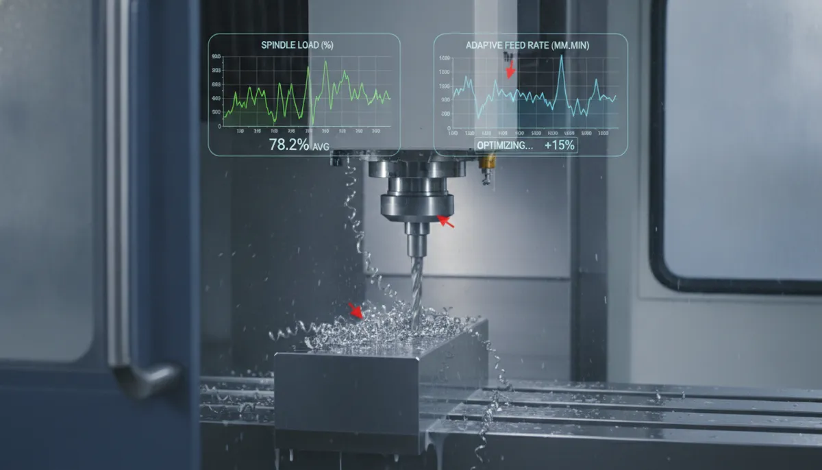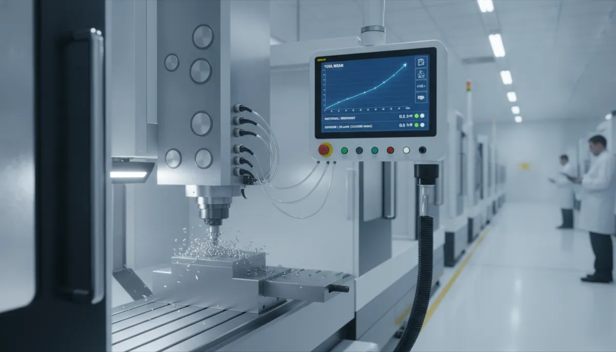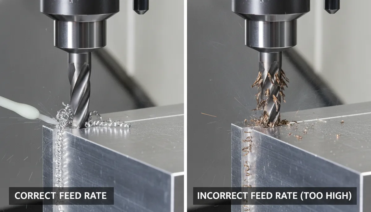
CNC feed rate — the speed at which a cutting tool advances through a workpiece — is one of the most critical parameters in CNC machining. Set it too low and your tool rubs instead of cuts, generating heat and premature wear. Set it too high and you risk tool breakage, chatter, and scrapped parts. Whether you are programming your first CNC mill or optimising a production turning cell, understanding CNC feed rate in IPM, IPR, and MMPM is the foundation of consistent, cost-effective machining. This guide from QFCNCMachine breaks down every key concept — from feed per tooth to feed per revolution — with real formulas, worked examples, and material-specific reference values.
1. Why CNC Feed Rate Optimisation Matters in Today’s Manufacturing Market
The global CNC machine tools market was valued at USD 101.22 billion in 2025 and is projected to reach USD 168.4 billion by 2036 at a CAGR of approximately 7.2%, driven by increasing demand for high-speed, high-precision machining in aerospace, automotive, and medical device manufacturing (Fortune Business Insights, 2025). A parallel analysis by Meticulous Research values the global CNC machine tools market at USD 84.3 billion in 2025, growing to USD 168.4 billion by 2036, with feed rate optimisation and adaptive control technology identified as key differentiators for manufacturers seeking to reduce cycle time and tooling costs (Meticulous Research, 2025).
At the broader machine tools level, Grand View Research values the global market at USD 117.2 billion in 2025, projected to reach USD 183.5 billion by 2033 at a CAGR of 5.8%, with productivity improvements from optimised feeds and speeds cited as a primary purchasing driver across European and Southeast Asian manufacturing clusters (Grand View Research, 2025). MarketsandMarkets similarly projects the machine tools market to grow from USD 82.40 billion in 2026 to USD 110.97 billion by 2033, noting that incorrect feed rate selection remains one of the top causes of preventable tooling waste in high-mix, low-volume production environments (MarketsandMarkets, 2026). Getting your CNC feed rate right is not just a technical detail — it is a direct lever on profitability.
2. CNC Feed Rate Definition: IPM, IPR, and MMPM Explained
2.1 What Is CNC Feed Rate?
CNC feed rate is the speed at which the cutting tool moves relative to the workpiece during a machining operation. It is distinct from cutting speed (SFM or m/min), which describes how fast the cutting edge moves through the material. Feed rate determines chip thickness — too thin and the tool rubs; too thick and it breaks. The correct feed rate produces consistent, well-formed chips that carry heat away from the cutting zone, protecting both the tool and the workpiece surface.
2.2 IPM — Inches Per Minute (Milling Standard)
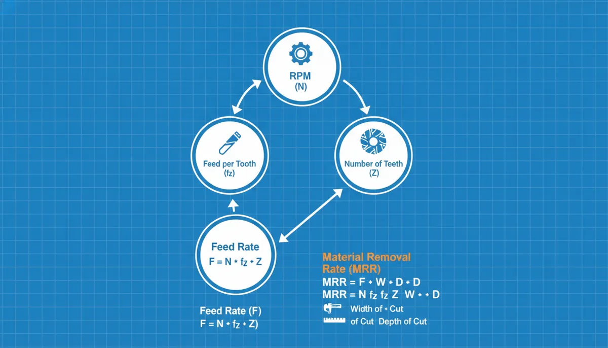
IPM (inches per minute) is the standard feed rate unit for CNC milling operations. It describes the linear distance the tool travels through the material per minute. IPM is calculated using the fundamental feed rate formula:
For example: a 2-flute end mill at 10,000 RPM with a recommended FPT of 0.002″ gives:
IPM = 10,000 × 2 × 0.002 = 40 IPM
IPM is the most intuitive unit for milling because it directly corresponds to table movement speed and is the standard output of most CAM software packages.
2.3 IPR — Inches Per Revolution (Turning Standard)
IPR (inches per revolution) is the standard feed rate unit for CNC turning and boring operations. It describes how far the tool advances per single revolution of the workpiece. IPR directly controls chip thickness and surface finish:
For roughing passes, typical IPR values are 0.010–0.020″; for finishing passes, 0.002–0.005″. Because IPR is independent of spindle speed, it remains consistent even when CSS (constant surface speed) mode changes the RPM as the tool moves across different diameters — making it the preferred unit for lathe programming.
2.4 MMPM — Millimetres Per Minute (Metric Standard)
MMPM (millimetres per minute) is the metric equivalent of IPM, used across Europe, Southeast Asia, and any shop working to ISO drawing standards. The conversion is straightforward:
For example, 40 IPM = 1,016 MMPM. All QFCNCMachine machining centers support seamless switching between IPM and MMPM units, allowing operators to work in their preferred system without manual conversion.
2.5 Feed Per Tooth (FPT): The Key to Tool Life
Feed per tooth (FPT) — also called chip load — is the distance the tool advances per cutting edge per revolution. It is the most important single parameter for tool life and surface finish. Too low an FPT causes rubbing and heat buildup (accelerating wear); too high causes chipping or breakage. FPT is determined by tool material, coating, workpiece material, and machine rigidity. Always start with the cutting tool manufacturer’s recommended FPT and adjust based on chip appearance and surface finish.
3. CNC Feed Rate Reference Table: Material × Tool × Recommended Values
Use the table below as a starting-point reference for common material and tool combinations. Always verify against your specific tool manufacturer’s data sheet and adjust based on machine rigidity and depth of cut.
| Material | Tool Type | Recommended RPM | FPT (inches) | Recommended IPM | MMPM Equivalent |
|---|---|---|---|---|---|
| 6061 Aluminium | 1/4″ 2-flute carbide | 18,000–24,000 | 0.002–0.004″ | 72–192 IPM | 1,829–4,877 MMPM |
| 6061 Aluminium | 1/2″ 3-flute carbide | 10,000–14,000 | 0.003–0.005″ | 90–210 IPM | 2,286–5,334 MMPM |
| Mild Steel (1018) | 1/2″ 4-flute carbide | 2,500–4,000 | 0.002–0.004″ | 20–64 IPM | 508–1,626 MMPM |
| 4140 Alloy Steel | 3/4″ 4-flute carbide | 1,200–1,800 | 0.003–0.005″ | 14–36 IPM | 356–914 MMPM |
| 304 Stainless Steel | 1/2″ 4-flute carbide | 1,500–2,500 | 0.001–0.003″ | 6–30 IPM | 152–762 MMPM |
| Titanium (Ti-6Al-4V) | 1/2″ 4-flute carbide | 800–1,500 | 0.001–0.002″ | 3–12 IPM | 76–305 MMPM |
| Hardwood / MDF | 1/4″ 2-flute upcut spiral | 16,000–20,000 | 0.004–0.008″ | 128–320 IPM | 3,251–8,128 MMPM |
| Operation | Unit | Roughing Range | Finishing Range | Notes |
|---|---|---|---|---|
| CNC Turning (Steel) | IPR | 0.010–0.020″ | 0.002–0.005″ | Use CSS mode for consistent finish |
| CNC Turning (Aluminium) | IPR | 0.015–0.030″ | 0.003–0.008″ | Higher IPR acceptable due to lower hardness |
| CNC Milling (Steel) | IPM | 10–40 IPM | 5–15 IPM | Reduce by 20–30% for stainless |
| CNC Milling (Aluminium) | IPM / MMPM | 80–200 IPM | 40–100 IPM | Use high-helix tools for chip evacuation |
4. Real-World CNC Feed Rate Problems Solved
4.1 The Broken End Mill: Aluminium Desktop CNC (USA)
Pain Point: A hobbyist machining 6061 aluminium on a desktop CNC kept breaking 1/8″ 2-flute end mills. They were running 20 IPM at 10,000 RPM. The chips were fine dust — a clear sign of insufficient chip load (rubbing, not cutting), which generates heat and causes premature tool failure.
Solution: Using the standard formula with the recommended FPT of 0.002″ for 1/8″ carbide in aluminium:
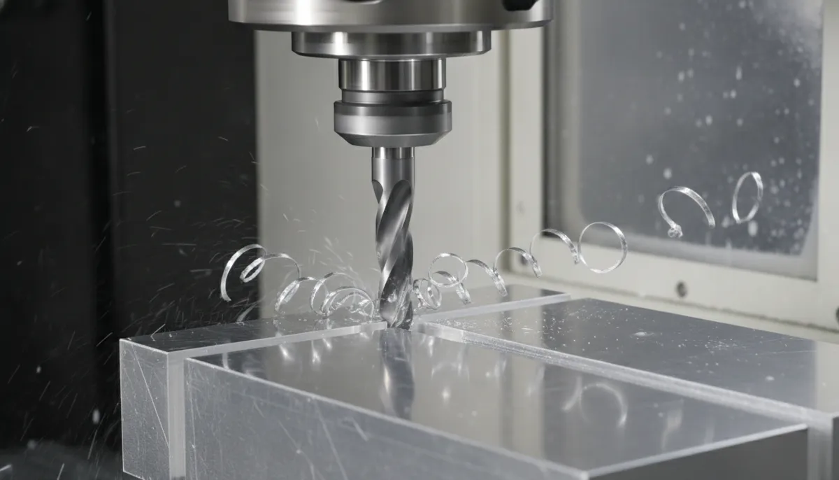
Doubling the feed rate to 40 IPM produced thick, curling chips, eliminated tool breakage entirely, and improved surface finish. The operator reported zero broken end mills across the following 3-month production period.
“I was breaking a 1/8″ end mill every other session and couldn’t figure out why. Bella’s team walked me through the chip load calculation — turns out I was running at half the correct feed rate. After adjusting to 40 IPM, I haven’t broken a single tool in three months. The formula is simple once someone explains it properly. QFCNCMachine’s support was patient and genuinely helpful for a beginner like me.”
4.2 Surface Finish Nightmare in 4140 Steel (Germany)
Pain Point: A German job shop milling 4140 alloy steel with a 3/4″ 4-flute carbide end mill was experiencing rough surface finish and premature tool burning. They were running 300 SFM with 0.005 IPR — but applying IPR logic to a milling operation, which caused inconsistent chip load across the cutter.
Solution: Converting to IPM-based thinking with the correct FPT for roughing 4140 (0.004″ per tooth):
IPM = 1,528 × 4 teeth × 0.004″ = ~24 IPM
Switching from 7.5 IPM (the incorrect IPR-derived value) to 24 IPM improved surface finish from Ra 3.2 µm to Ra 1.6 µm and extended tool life by over 50% by ensuring proper chip formation rather than rubbing.
“We were applying turning logic to a milling operation — using IPR instead of calculating proper IPM from feed per tooth. The result was a terrible surface finish and tools burning out in under an hour. QFCNCMachine’s technical team identified the error immediately and gave us the correct formula. After switching to 24 IPM, our surface finish halved in roughness value and tool life more than doubled. A simple fix that saved us significant tooling cost every month.”
4.3 Chatter in Thin-Wall Aluminium Pockets (Malaysia)
Pain Point: A Malaysian aerospace subcontractor machining thin-wall 7075 aluminium pockets experienced severe chatter at 100 IPM with a 1/2″ 3-flute end mill at 12,000 RPM. The vibration was causing dimensional errors of up to 0.08 mm on wall thickness — outside the ±0.05 mm drawing tolerance.
Solution: Reducing RPM to 8,000 and recalculating feed to maintain the target chip load of 0.003″ per tooth:
The lower RPM reduced the excitation frequency away from the part’s natural resonance frequency, eliminating chatter. At 72 IPM, all wall thickness measurements passed CMM inspection within ±0.03 mm — well within tolerance.
“Chatter on thin-wall aluminium was our biggest quality problem — we were scrapping nearly one in five parts due to wall thickness variation. QFCNCMachine’s applications team diagnosed the issue as resonance at our original RPM and showed us how to recalculate feed at a lower speed to maintain chip load. The fix took 10 minutes to implement. Our scrap rate on thin-wall parts dropped from around 20% to under 3%, and every part now passes CMM first time. The technical support alone has paid for itself many times over.”
5. Pros & Cons of Each CNC Feed Rate Unit
✅ IPM (Inches Per Minute) — Pros
- Industry standard for CNC milling operations
- Directly corresponds to table movement speed
- Simple formula: IPM = RPM × teeth × FPT
- Standard output of all major CAM software
- Easy to verify with a stopwatch on the machine
❌ IPM (Inches Per Minute) — Cons
- Not ideal for turning — IPR is more relevant for lathes
- Must be recalculated if RPM changes
- Can mislead beginners who confuse it with cutting speed
- Requires unit conversion for metric drawings (÷ 25.4 for MMPM)
✅ IPR (Inches Per Revolution) — Pros
- Standard unit for CNC turning and boring
- Directly controls chip thickness and surface finish
- Consistent chip load even when CSS changes RPM
- Simplifies lathe programming across different diameters
❌ IPR (Inches Per Revolution) — Cons
- Less intuitive for milling — requires conversion to IPM
- Confusing for beginners mixing milling and turning operations
- Not directly visible as a physical speed on the machine
✅ MMPM (Millimetres Per Minute) — Pros
- ISO metric standard — used across Europe and Southeast Asia
- Direct compatibility with metric tool manufacturer data sheets
- No conversion needed for metric drawings and tolerances
- Preferred by most European and Asian CAM systems
❌ MMPM (Millimetres Per Minute) — Cons
- Requires conversion for US/imperial tool data (× 25.4 from IPM)
- Large numbers can feel less intuitive (e.g., 2,540 MMPM vs 100 IPM)
- Some older US-market CAM software defaults to IPM only
6. Frequently Asked Questions About CNC Feed Rate
What is the difference between CNC feed rate and cutting speed?
Cutting speed (measured in SFM — surface feet per minute, or m/min) is the velocity at which the cutting edge moves relative to the workpiece surface. It determines the RPM of the spindle based on tool diameter. CNC feed rate (IPM, IPR, or MMPM) is how fast the tool advances through the material. They work together: cutting speed sets the RPM, and feed rate (via FPT) sets the chip load. Both must be balanced — correct cutting speed with incorrect feed rate will still produce poor results.
How do I calculate CNC feed rate for a milling operation?
Use the three-step process: Step 1 — determine RPM from cutting speed: RPM = (SFM × 3.82) ÷ tool diameter (inches). Step 2 — look up the recommended FPT for your material and tool from the manufacturer’s data sheet (e.g., 0.002–0.004″ per tooth for 1/4″ carbide in aluminium). Step 3 — calculate IPM: IPM = RPM × number of teeth × FPT. For metric, multiply the result by 25.4 to get MMPM.
What happens if CNC feed rate is too high or too low?
Too low: The tool rubs rather than cuts, generating excessive heat, causing work hardening (especially in stainless steel and titanium), and accelerating flank wear. Chips appear as fine dust. Too high: Chip load exceeds the tool’s structural capacity, causing chipping, breakage, chatter, and degraded surface finish. Chips appear as thick, irregular fragments. The target is a balanced chip load producing consistent, curled chips that carry heat away from the cutting zone.
Should I use IPM or IPR for my CNC lathe?
Always use IPR for CNC turning and boring operations. IPR directly controls chip thickness regardless of spindle speed changes — critical when using CSS (constant surface speed) mode, where RPM changes continuously as the tool moves across different diameters. If your lathe controller only accepts IPM, convert using: IPM = RPM × IPR. For metric lathes, use mm/rev (millimetres per revolution), which is the direct metric equivalent of IPR.
How does feed per tooth affect CNC tool life?
FPT is the single most critical factor for tool life. Too low FPT (below ~0.001″ for most carbide tools) causes the cutting edge to rub rather than shear, generating heat that accelerates crater wear and coating breakdown. Too high FPT overloads the cutting edge, causing micro-chipping or catastrophic breakage. The optimal FPT varies by tool material (carbide vs HSS), coating (TiAlN, TiCN, uncoated), workpiece material hardness, and machine rigidity. Always start at the lower end of the manufacturer’s recommended range and increase in 10% increments while monitoring chip colour and appearance.
What is the warranty and return policy for QFCNCMachine equipment?
All QFCNCMachine machining centers come with a 2-year warranty covering manufacturing defects and component failures under normal operating conditions. In the event of a confirmed quality issue, we support full replacement or refund. Please note that returns without a quality-related reason are not supported — our team will work with you to diagnose and resolve any performance issues before a return is considered. Contact Bella directly at bella@qfcncmachine.com or +86 151 1824 3737 for any warranty or after-sales enquiry.
Ready to Optimise Your CNC Feed Rate?
With 15+ years of CNC machining experience and 750+ customers across Europe, North America, and Southeast Asia since 2010, QFCNCMachine’s engineering team can help you select the right machine, set up your first job, and dial in feeds and speeds for your specific material and tooling. All machines come with a 2-year warranty and full after-sales support from our Dongguan facility.
References
- Mordor Intelligence. CNC Machines Market Size, Share & Growth Trends Report, 2025–2031. Retrieved August 2026 from https://www.mordorintelligence.com/industry-reports/cnc-machines-market
- Fortune Business Insights. CNC Machine Tools Market Size, Share & Industry Analysis, 2025–2034. Retrieved August 2026 from https://www.fortunebusinessinsights.com/industry-reports/computer-numerical-controls-cnc-machine-tools-market-101707
- Grand View Research. Machine Tools Market Size, Share & Trends Analysis Report, 2025–2033. Retrieved August 2026 from https://www.grandviewresearch.com/industry-analysis/machine-tools-market
- MarketsandMarkets. Machine Tools Market Size, Share & Analysis, 2026–2033. Retrieved August 2026 from https://www.marketsandmarkets.com/Market-Reports/machine-tools-market-168345068.html