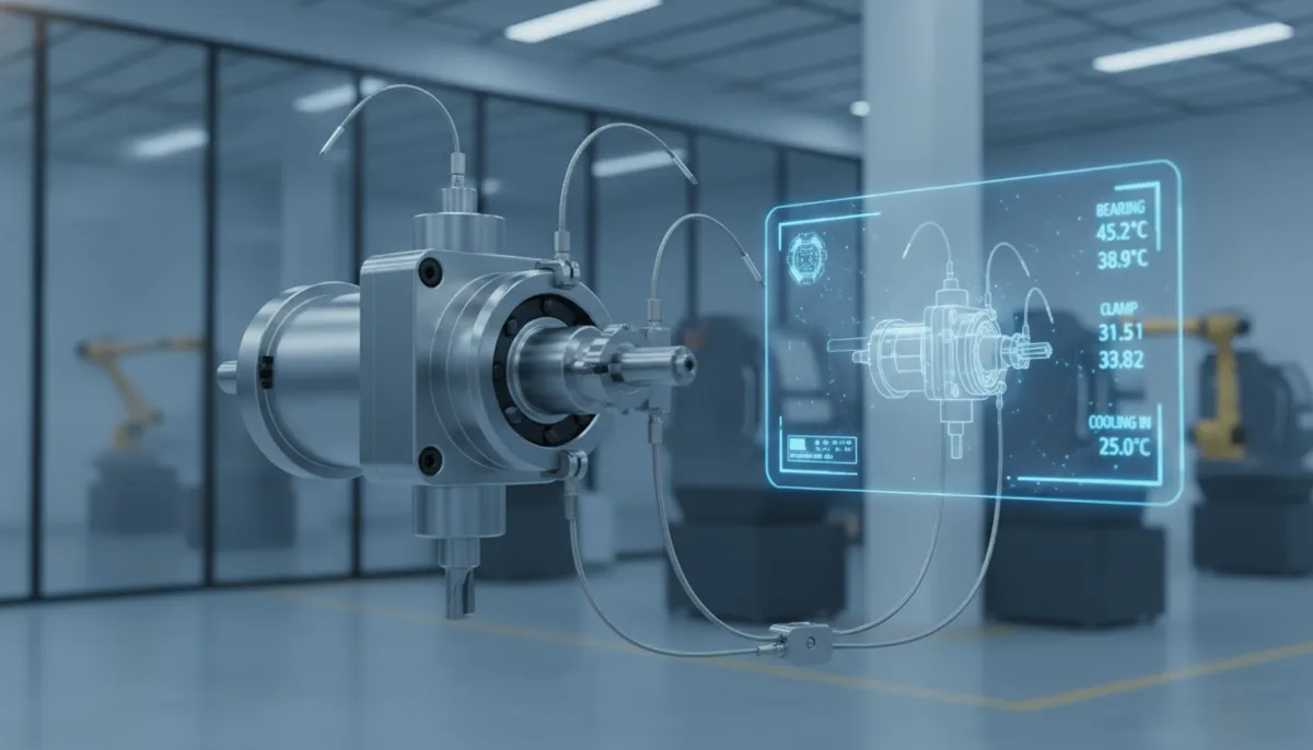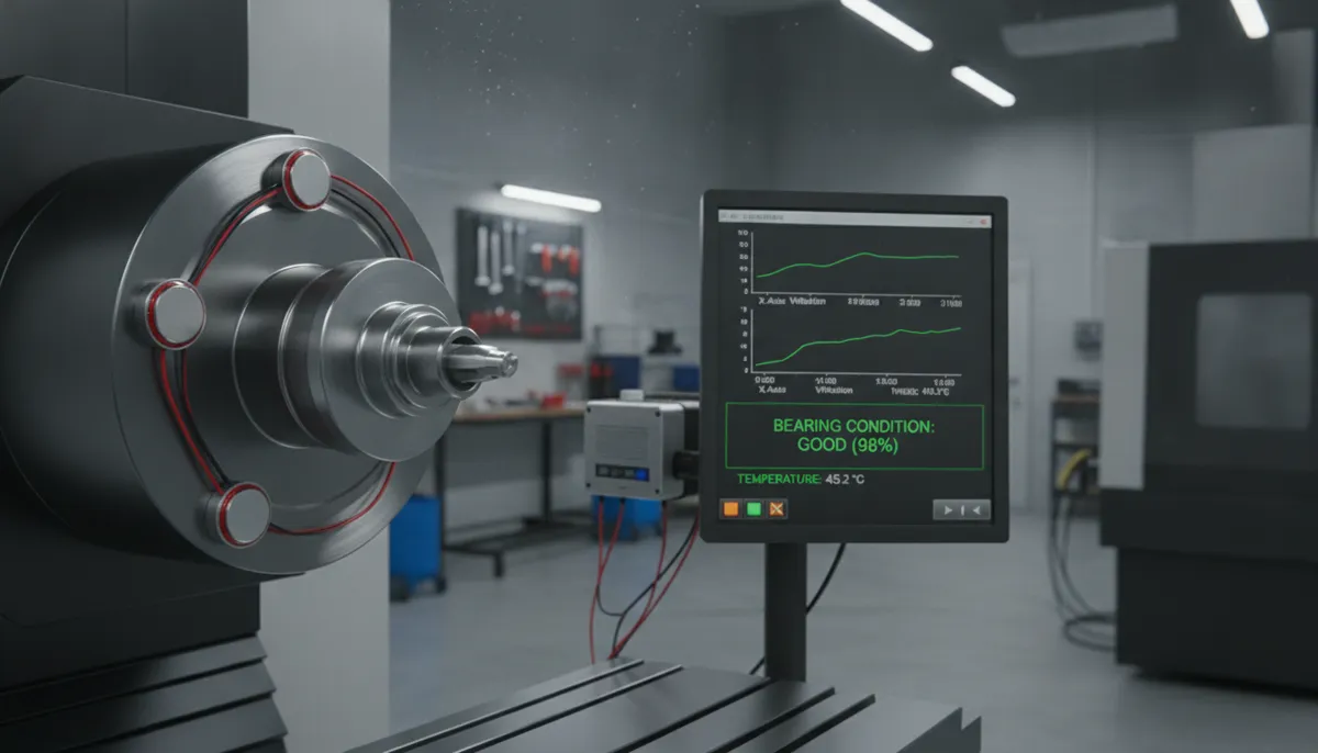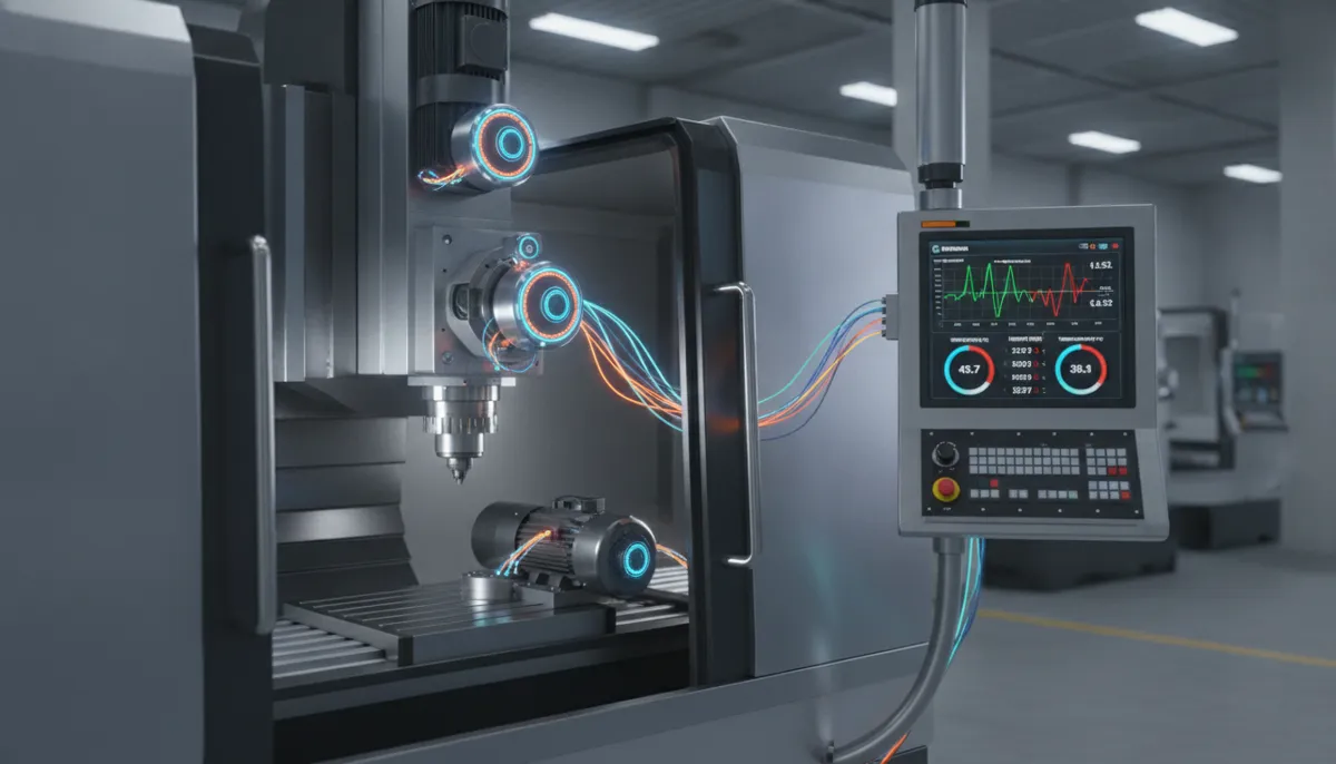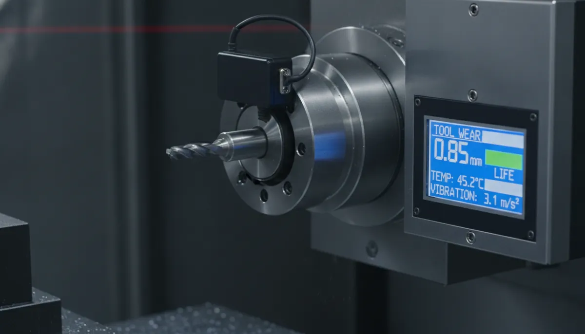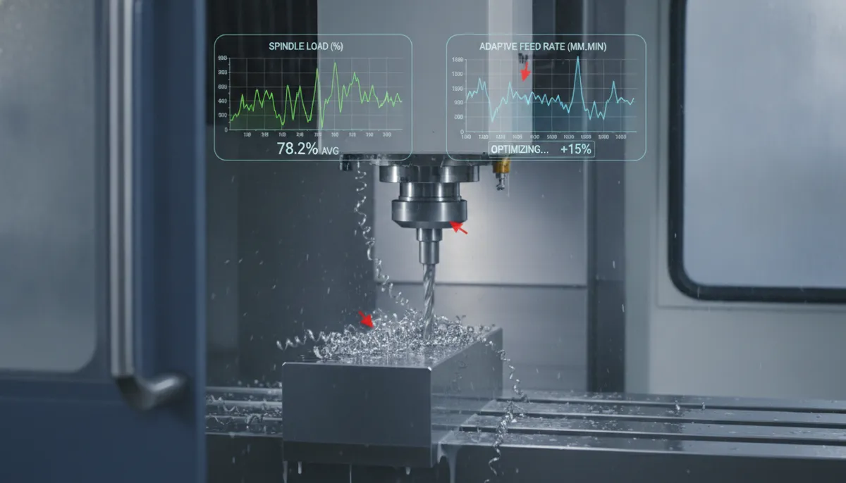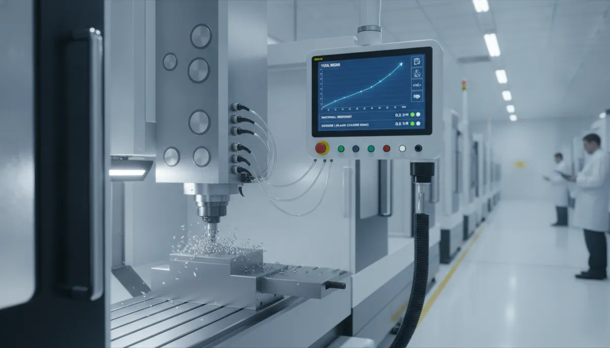
A CNC axis is a controlled direction of movement that determines how a CNC machine positions its cutting tool relative to the workpiece. Understanding CNC axes — from the three fundamental linear axes (X, Y, Z) to the rotary axes (A, B, C) that unlock complex multi-surface machining — is the essential first step for anyone learning CNC programming, selecting a new machine, or optimising an existing production workflow. This guide from QFCNCMachine breaks down every axis type, explains how they work together, and shows you exactly which axis configuration matches your machining requirements.

1. Why CNC Axis Technology Is Driving Global Manufacturing Growth
The global machining centers market — the segment most directly shaped by advances in multi-axis CNC technology — was valued at USD 23.67 billion in 2026 and is forecast to reach USD 30.75 billion by 2031 at a CAGR of 5.37%, with multi-axis (4-axis and 5-axis) machining centers representing the fastest-growing product category as manufacturers seek to reduce setups and improve part complexity capability (Mordor Intelligence, 2024). A parallel analysis by MarketsandMarkets projects the machining centers market to grow from USD 22.54 billion in 2026 to USD 30.82 billion by 2033 at a CAGR of 4.6%, noting that advanced 5-axis and multi-axis configurations are the primary technology driver behind market expansion in aerospace, automotive, and medical device manufacturing (MarketsandMarkets, 2026).
At the sub-segment level, the global 5-axis CNC machining centers market alone is forecast to grow by USD 875.4 million between 2024 and 2029 at a CAGR of 6.3%, driven by the aerospace and medical sectors’ demand for complex single-setup machining that only multi-axis configurations can deliver (Technavio, 2025). The broader machining centers market is projected to reach USD 47.7 billion by 2035 from USD 27.5 billion in 2025, growing at a CAGR of 5.7% — underscoring that investment in the right CNC axis configuration today is a long-term competitive advantage for manufacturers across all sectors (Market.us, 2025).
2. What Is a CNC Axis? Core Definition and Coordinate System
A CNC axis is a controlled direction of motion along which — or around which — a machine component moves under computer numerical control. CNC machines use the standard Cartesian coordinate system as their foundation, assigning three linear axes (X, Y, Z) for straight-line movements and three rotary axes (A, B, C) for angular movements around those linear axes.
The three linear axes are defined as follows:
- X axis: Left-to-right horizontal movement (the longest travel axis on most machining centers)
- Y axis: Front-to-back horizontal movement (table or saddle travel)
- Z axis: Vertical up-and-down movement (spindle depth / tool engagement)
The three rotary axes rotate around their corresponding linear axes:
- A axis: Rotation around the X axis (tilting front-to-back)
- B axis: Rotation around the Y axis (tilting left-to-right)
- C axis: Rotation around the Z axis (rotating the table or spindle)
The combination of these axes determines how many surfaces of a part can be machined in a single setup — which directly impacts cycle time, dimensional accuracy, and production cost. Every additional axis reduces the number of manual repositioning steps required, eliminating the fixturing errors and tolerance stack-up that are the primary cause of dimensional inconsistency in multi-operation parts.
3. CNC Axis Configurations Explained: 3-Axis to 6-Axis
3.1 3-Axis CNC Machining (X, Y, Z)
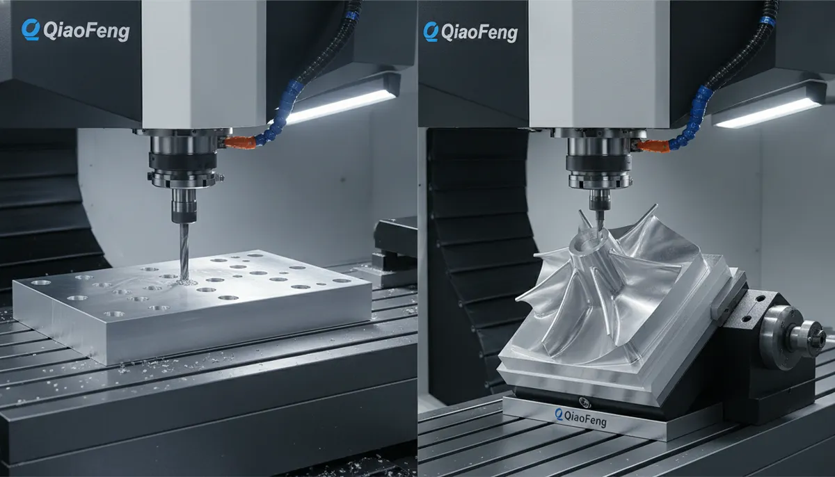
The most common CNC configuration, 3-axis machining moves the cutting tool linearly along X, Y, and Z. It is ideal for flat parts, 2D profiles, pockets, and simple 2.5D geometries. The tool always approaches the workpiece from a fixed vertical direction, which means undercuts and angled features require manual repositioning. For the majority of prismatic parts — brackets, plates, housings, and fixtures — 3-axis machining delivers excellent results at the lowest cost per part.
3.2 4-Axis CNC Machining (X, Y, Z + A)
Adding a rotary A axis (rotation around X) to a 3-axis machine enables continuous machining of cylindrical parts and helical features without manual indexing. The workpiece rotates while the cutting tool moves linearly, enabling helical grooves, gear teeth, cam profiles, and features on multiple faces of a part in a single setup. 4-axis machining is the standard configuration for shaft work, roller engraving, and cylindrical component production.
3.3 5-Axis CNC Machining (X, Y, Z + A + B or C)
5-axis machining adds a second rotary axis (typically B or C) to the 4-axis configuration, allowing the cutting tool to approach the workpiece from virtually any angle. This eliminates the need to reposition the part for angled surfaces, undercuts, and complex 3D contours. The result is dramatically reduced setup time, better surface finish (the tool can always maintain optimal cutting angle), and the ability to machine complex aerospace, medical, and mould components that are simply not achievable on 3- or 4-axis machines. 5-axis is the current industry standard for high-value precision components.
3.4 6-Axis CNC Machining (X, Y, Z + A + B + C)
6-axis machining adds the C axis (rotation around Z) to the full 5-axis configuration, providing complete articulation of both the tool and the workpiece simultaneously. This is the most advanced configuration available and is used for the most complex industrial applications: multi-sided turbine components, large structural aerospace parts, and complex medical implants where every surface must be machined to tight tolerances in a single continuous program. 6-axis machines represent the highest capital investment but deliver unmatched flexibility for the most demanding production requirements.
4. CNC Axis Configuration Comparison: Full Specification Overview
Use the table below to compare all four CNC axis configurations across the criteria that matter most for your application selection:
| Configuration | Axes | Typical Applications | Key Industries | Setup Reductions vs Manual | Relative Cost |
|---|---|---|---|---|---|
| 3-Axis | X, Y, Z | Flat parts, pockets, 2.5D profiles, plates | General engineering, education, prototyping | Moderate | $ Low |
| 4-Axis | X, Y, Z + A | Cylindrical parts, helical grooves, multi-face parts | Automotive, shaft manufacturing, engraving | High (eliminates manual indexing) | $$ Medium |
| 5-Axis | X, Y, Z + A + B/C | Impellers, moulds, implants, aerospace brackets | Aerospace, medical, mould & die, defence | Very High (single setup for complex parts) | $$$ High |
| 6-Axis | X, Y, Z + A + B + C | Turbine blades, large structural parts, complex implants | Aerospace, energy, advanced medical | Maximum (full articulation) | $$$$ Very High |
5. Key Features of QFCNCMachine CNC Axis Systems
5.1 High-Precision Linear Guides (X, Y, Z Axes)
QFCNCMachine’s X, Y, and Z axes are built with Japanese THK or HIWIN linear rails, delivering positional repeatability within 0.002 mm. High-precision linear guides eliminate the stick-slip motion and play that cause dimensional drift in cheaper guide systems. In practical terms, this means a mould maker can run a full 8-hour production shift and find the last part dimensionally identical to the first — a level of consistency that directly reduces scrap, rework, and inspection overhead.
5.2 Direct-Drive Rotary Axes (A, B, C Axes)
The rotary A, B, and C axes on QFCNCMachine’s multi-axis centers are equipped with direct-drive torque motors, eliminating the backlash inherent in worm gear or belt-driven rotary systems. Zero backlash means no lost motion during complex contouring — the tool follows the programmed path exactly, producing smooth surface finishes without post-machining polishing. This is particularly critical for medical implant surfaces (Ra ≤ 0.4 µm) and aerospace aerodynamic surfaces where surface finish directly impacts functional performance.
5.3 Intelligent Multi-Axis Synchronisation
QFCNCMachine’s CNC control system synchronises up to 6 axes simultaneously using look-ahead interpolation algorithms that anticipate direction changes and pre-calculate optimal feed rates. This eliminates the deceleration-acceleration dwell marks that appear on complex contoured surfaces when the controller cannot keep up with rapid direction changes. The result is faster cycle times and better surface quality on complex 5-axis tool paths — particularly on aerospace freeform surfaces and mould cavity contours.
5.4 Automatic Axis Calibration and Thermal Compensation
Built-in calibration routines on all QFCNCMachine axis systems compensate for thermal growth of the machine structure during operation. As the machine warms up over the first hour of a shift, the control system automatically applies measured compensation offsets to maintain dimensional accuracy — without requiring the operator to manually re-zero axes or run test cuts. This is critical for maintaining ±0.01 mm accuracy across full 8-hour production shifts in ambient temperature environments without climate control.
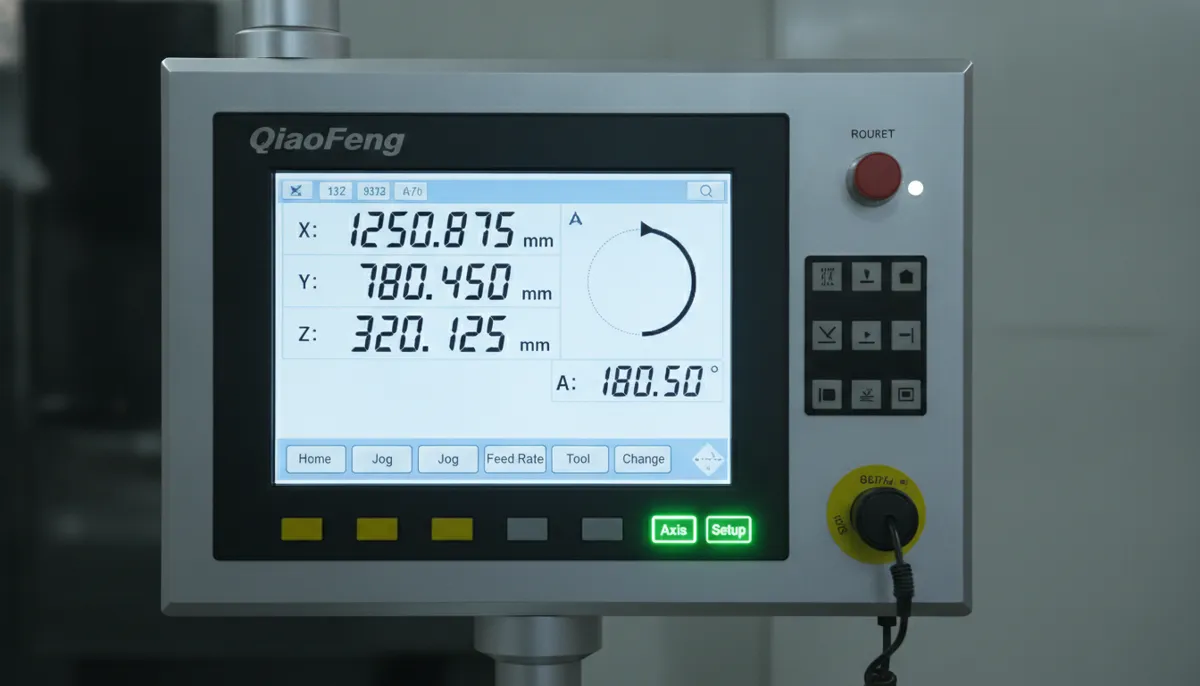
5.5 Beginner-Friendly Axis Setup Interface
QFCNCMachine’s touchscreen control interface includes a guided axis setup wizard that walks operators through workpiece coordinate system (WCS) setting, tool length measurement, and rotary axis positioning — the three most common sources of setup error for CNC beginners. The wizard reduces axis setup time from hours to minutes for new operators, and QFCNCMachine provides full video training resources and direct technical support from our Dongguan engineering team for all machine purchasers.
6. Real-World CNC Axis Applications & Customer Results
6.1 3-Axis Milling for Aluminium Structural Brackets — USA
A US-based contract manufacturer was producing aluminium structural brackets for the electronics industry using a manual mill, requiring three separate setups per part and achieving only ±0.05 mm positional accuracy on hole patterns. After switching to a QFCNCMachine 3-axis CNC machining center, all features were completed in a single setup. Positional accuracy improved to ±0.005 mm, production output increased by 75%, and the customer eliminated the dedicated deburring step that had been required to correct manual milling artefacts.
“We were running three setups per bracket on a manual mill and still couldn’t hold the hole pattern tolerance our customer required. The QFCNCMachine 3-axis center changed everything — one setup, ±0.005 mm accuracy, and we’re running 75% more parts per shift. The axis setup wizard meant our operator was running production parts within two days of installation. Bella’s team answered every technical question we had during commissioning. We’ve since ordered a second machine.”
6.2 4-Axis Helical Groove Machining on Steel Rollers — Germany
A German industrial components supplier needed to cut precise helical grooves on hardened steel rollers for a conveyor system application. Using their existing 3-axis machine, each roller required manual indexing between cuts, producing inconsistent groove pitch and requiring 100% manual inspection. After adding a QFCNCMachine 4-axis rotary unit (A axis), continuous helical interpolation was achieved — the CNC controlled linear and rotary motion simultaneously. Groove pitch consistency improved from ±0.08 mm to ±0.01 mm, and cycle time per roller was reduced by 55%.
“Manual indexing on our 3-axis machine was giving us ±0.08 mm pitch variation on the helical grooves — our customer’s assembly tolerance was ±0.02 mm, so we were failing every batch. The QFCNCMachine 4-axis rotary unit solved this completely. We’re now holding ±0.01 mm pitch consistently, cycle time is down 55%, and we’ve eliminated 100% manual inspection. The direct-drive A axis has zero backlash — you can feel the difference in the surface finish immediately. Two-year warranty and local European service support sealed the decision.”
6.3 5-Axis Impeller Machining for Pump Manufacturing — Vietnam
A Vietnamese pump and fluid equipment manufacturer was machining stainless steel impeller blades on a 3-axis machine, requiring five manual repositioning setups per impeller and achieving poor blade surface finish (Ra 3.2 µm) due to suboptimal tool approach angles. After upgrading to a QFCNCMachine 5-axis machining center (X, Y, Z + A + C), all blade surfaces were machined in a single setup with the tool maintaining optimal cutting angle throughout. Surface finish improved to Ra 0.8 µm, cycle time per impeller was reduced by 45%, and the customer was able to take on higher-value aerospace pump contracts that previously required outsourcing.
“Our impellers were taking five setups on the 3-axis machine and the blade finish was still not good enough for our premium pump range. The QFCNCMachine 5-axis center machined the entire impeller in one setup — Ra 0.8 µm on the blades, 45% faster cycle time, and we no longer need to outsource the high-spec aerospace pump work. The intelligent axis synchronisation on complex blade paths is genuinely impressive. Bella understood our application requirements immediately and recommended the correct axis configuration for our part family. We are very satisfied with the investment.”
7. Pros & Cons of Each CNC Axis Configuration
✅ 3-Axis CNC — Pros
- Lowest purchase and operating cost
- Simplest programming — ideal for beginners
- Fastest setup for flat and prismatic parts
- Widest range of compatible CAM software
- Easiest maintenance and calibration
❌ 3-Axis CNC — Cons
- Cannot machine undercuts or angled features without repositioning
- Multiple setups required for multi-face parts
- Tolerance stack-up increases with each repositioning
- Not suitable for complex 3D contours
✅ 4-Axis CNC — Pros
- Enables continuous helical and cylindrical machining
- Eliminates manual indexing for multi-face parts
- Significantly improves consistency on rotational parts
- Moderate cost increase over 3-axis
- Retrofittable to many existing 3-axis machines
❌ 4-Axis CNC — Cons
- Cannot tilt the tool — limited to rotation around one axis
- Requires 4-axis-capable CAM post-processor
- More complex setup than 3-axis for beginners
- Not suitable for complex 3D freeform surfaces
✅ 5-Axis CNC — Pros
- Single-setup machining of complex 3D geometries
- Optimal tool angle maintained throughout — best surface finish
- Eliminates tolerance stack-up from multiple setups
- Enables aerospace, medical, and mould work impossible on 3-axis
- Reduces total cycle time despite higher machine cost
❌ 5-Axis CNC — Cons
- Highest cost among standard configurations
- Complex programming — requires experienced CAM operator
- More demanding maintenance and calibration
- Overkill for simple prismatic or cylindrical parts
8. Frequently Asked Questions About CNC Axes
What is the difference between 3-axis and 5-axis CNC machining?
A 3-axis CNC machine moves the cutting tool linearly along X, Y, and Z — it can machine flat surfaces, pockets, and simple 2.5D profiles, but the tool always approaches from a fixed vertical direction. A 5-axis machine adds two rotary axes (typically A and C, or A and B), allowing the tool to approach the workpiece from virtually any angle. This enables complex geometries — impellers, undercuts, contoured surfaces, and multi-face parts — in a single setup, eliminating repositioning errors and dramatically improving surface finish on angled features. For beginners, 3-axis is the recommended starting point; 5-axis is the standard for high-value precision components.
What do the A, B, and C axes mean in CNC?
A, B, and C are the three rotary axes in the CNC coordinate system. The A axis rotates around the X axis (tilting the workpiece or tool front-to-back). The B axis rotates around the Y axis (tilting left-to-right). The C axis rotates around the Z axis (rotating the table or spindle). On a typical 5-axis machining center, you will have X, Y, Z (linear) plus two of the three rotary axes — most commonly A and C (table tilts and rotates) or A and B (spindle tilts in two planes). The specific combination depends on the machine’s structural design.
How do I choose the right number of CNC axes for my projects?
Start by analysing your most complex part. If you primarily machine 2D or 2.5D parts (brackets, plates, simple housings), a 3-axis machine is sufficient and most cost-effective. If you regularly machine cylindrical parts (shafts, rollers, round components with features on multiple faces), add a rotary A axis for 4-axis capability. If you machine complex 3D organic shapes (impellers, turbine blades, mould cavities, medical implants), invest in a 5-axis machine. QFCNCMachine offers modular axis configurations and retrofit options — contact our team to discuss your specific part family before making a decision.
Can I retrofit a rotary axis to my existing 3-axis CNC machine?
Yes — many QFCNCMachine customers add a 4th-axis rotary table to their existing 3-axis machines. The requirements are: a CNC controller that supports 4-axis simultaneous motion, a compatible CAM post-processor, and sufficient table space for the rotary unit. QFCNCMachine offers retrofit rotary axis kits with full installation documentation and commissioning support. A typical 4-axis retrofit costs approximately 20–30% of a new dedicated 4-axis machine and can significantly expand your cylindrical and multi-face machining capability without replacing the entire machine.
How do I maintain CNC axis accuracy over time?
Axis accuracy degrades primarily through three mechanisms: linear guide and ball screw wear, thermal expansion during operation, and contamination of guideways. To maintain accuracy: clean and lubricate linear guides and ball screws according to the manufacturer’s schedule (typically every 500 operating hours); use the machine’s built-in thermal compensation routines to offset thermal growth during warm-up; avoid exceeding maximum feed rates and cutting forces specified for each axis; and perform a ballbar test annually to detect and quantify any developing wear. QFCNCMachine provides a complete maintenance schedule and checklist with every machine, and our after-sales team is available for remote diagnostic support.
What is the warranty and return policy for QFCNCMachine axis systems?
All QFCNCMachine CNC machines and axis systems come with a 2-year warranty covering manufacturing defects and premature component failure under normal operating conditions. In the event of a confirmed quality issue, we support full repair, replacement, or refund. Please note that returns are not accepted for non-quality reasons — our team conducts thorough pre-shipment inspection and functional testing on every machine to ensure it meets specification before dispatch. For any warranty or technical enquiry, contact Bella directly at bella@qfcncmachine.com or +86 151 1824 3737.
Not Sure Which CNC Axis Configuration Is Right for You?
With 15+ years of CNC machining expertise and 750+ customers across Europe, North America, and Southeast Asia since 2010, QFCNCMachine’s engineering team can review your part family and recommend the optimal axis configuration for your application and budget. All machines come with a 2-year warranty and full commissioning support from our Dongguan facility.
References
- Mordor Intelligence. Machining Centers Market Size, Share & Growth Trends Report, 2024. Retrieved August 2026 from https://www.mordorintelligence.com/industry-reports/machining-centers-market
- MarketsandMarkets. Machining Centers Market Size, Share, and Growth Report, 2026–2033. Retrieved August 2026 from https://www.marketsandmarkets.com/Market-Reports/machining-centers-market-168459068.html
- Technavio. 5-Axis CNC Machining Centers Market Size and Industry Analysis, 2024–2029. Retrieved August 2026 from https://www.technavio.com/report/5-axis-cnc-machining-centers-market-industry-analysis
- Market.us. Machining Centers Market Size, Share & Growth Forecast, 2025–2035. Retrieved August 2026 from https://market.us/report/machining-centers-market/