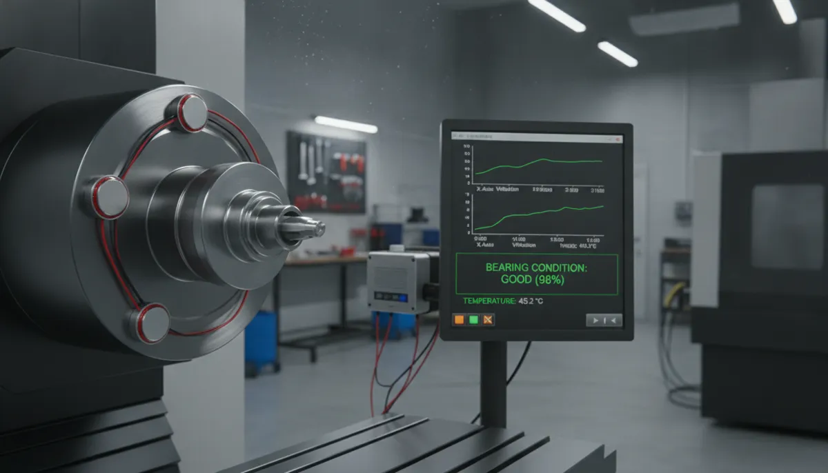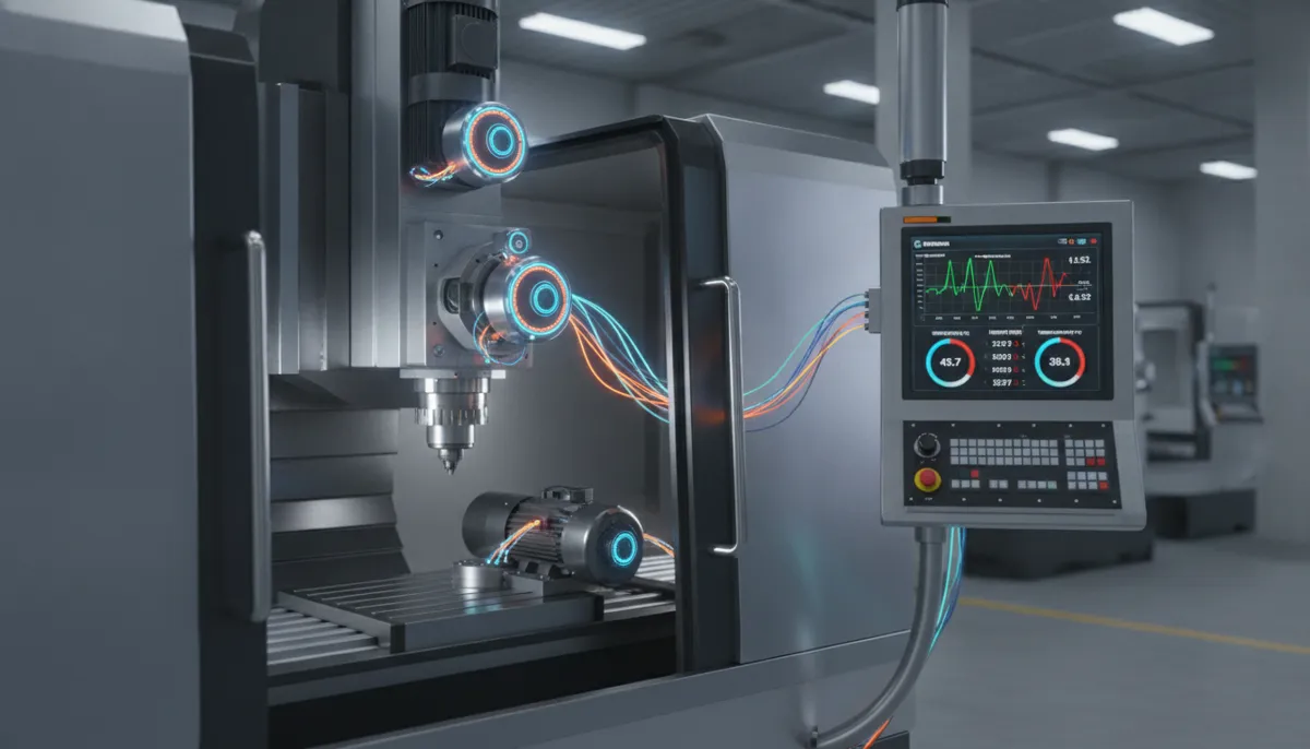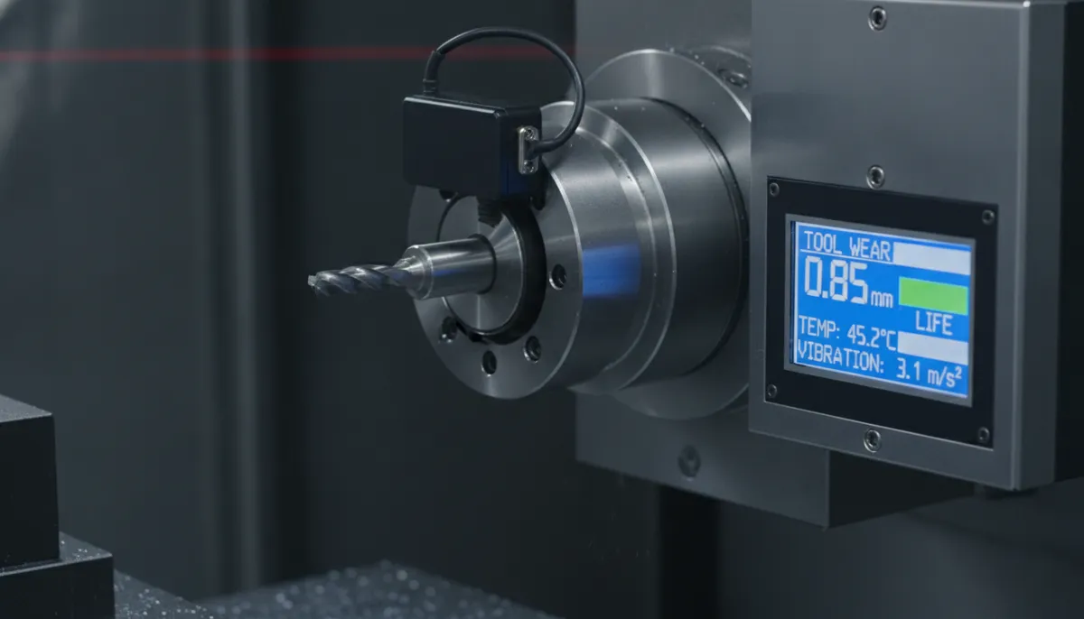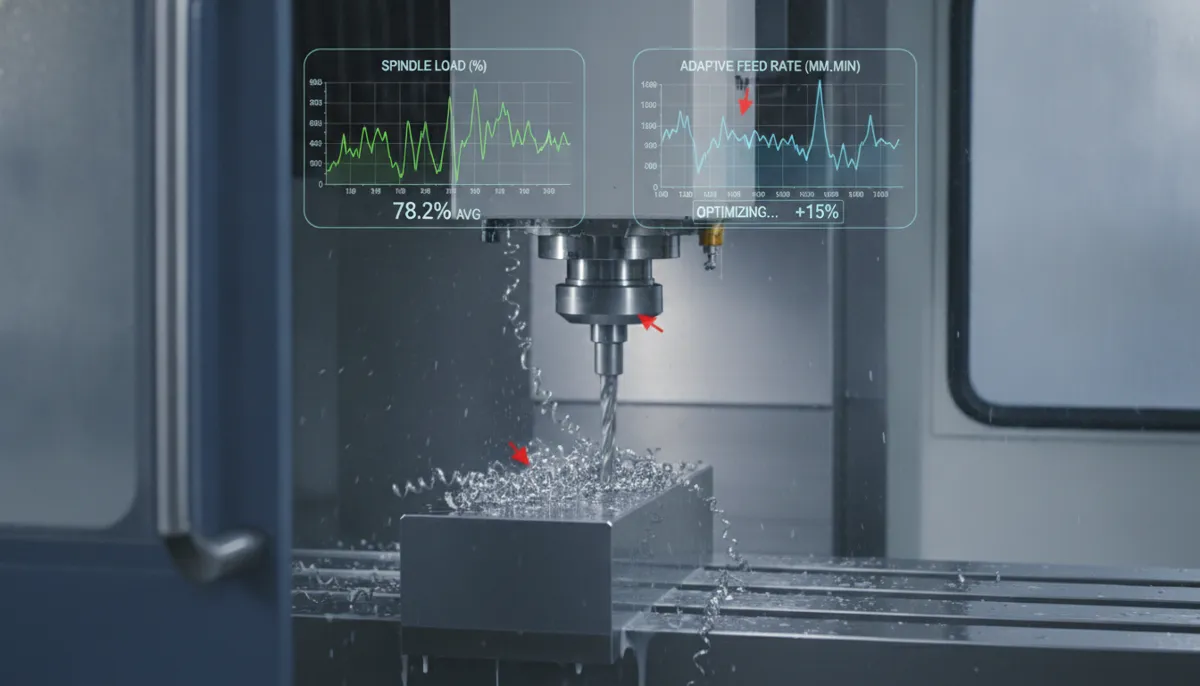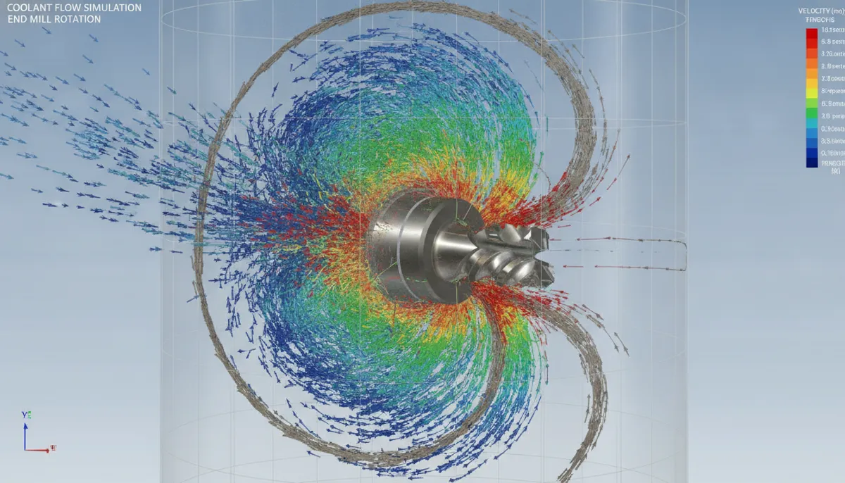
In precision CNC machining, coolant flow is far more than keeping the tool wet — it is the primary mechanism for controlling heat, evacuating chips, and protecting surface integrity. CNC CFD coolant simulation, powered by computational fluid dynamics (CFD), enables process engineers and manufacturing teams to visualize, model, and optimize coolant behavior in full detail before a single part is cut. By replacing guesswork with simulation-validated data, CNC CFD coolant analysis reduces thermal distortion, extends tool life by up to 30%, and delivers consistent surface quality across high-volume production runs. Since 2010, QiaoFeng — headquartered in Dalingshantown, Dongguan, Guangdong — has integrated CFD analysis into every machine design, serving 750+ manufacturers across North America, Europe, and Southeast Asia.
The Growing Importance of CNC CFD Coolant Optimization
Thermal management in machining is an increasingly critical competitive differentiator. According to Grand View Research (2024), the global cutting fluids market was valued at USD 9.6 billion in 2023 and is projected to grow at a CAGR of 4.2% through 2030, driven by rising demand from aerospace and automotive manufacturers for precision thermal control in difficult-to-machine alloy processing.
A peer-reviewed study published in the International Journal of Machine Tools and Manufacture (Courbon et al., 2021) demonstrated that optimized high-pressure coolant delivery reduced cutting zone temperatures in titanium alloy milling by 15–22°C compared to conventional flood cooling — directly correlating with a 28–35% improvement in tool life. Separately, Mordor Intelligence (2024) reports that manufacturers adopting simulation-driven coolant system design reduce coolant consumption by up to 30% while simultaneously improving chip evacuation efficiency, lowering both operating costs and environmental impact.
For manufacturers supplying aerospace, medical, and automotive OEMs, the ability to document simulation-validated thermal management is increasingly a qualification requirement — not merely a best practice.
1. Core Features of QiaoFeng’s CNC CFD Coolant System
1.1 CFD-Optimized Nozzle Geometry
QiaoFeng’s coolant nozzles are not off-the-shelf components — each is designed through iterative CNC CFD coolant simulation specific to the machine model and target application. CFD analysis determines the optimal nozzle exit angle, orifice diameter, and stand-off distance to ensure that every drop of coolant impinges on the cutting edge at the correct velocity and angle for maximum heat transfer and chip lift. In production environments, this translates to fewer rejected parts, longer tool runs, and reduced operator intervention.
1.2 Real-Time Closed-Loop Flow Monitoring
Integrated pressure, temperature, and flow-rate sensors feed live data back to the CNC controller. If coolant pressure drops due to filter loading, or if temperature rises above a defined threshold, the system automatically adjusts pump speed or triggers an operator alert. This closed-loop control maintains consistent cooling performance across an entire production shift — even as ambient conditions and coolant concentration drift.
1.3 Multi-Zone Independent Coolant Delivery
Rather than a single flood, QiaoFeng’s system directs coolant independently to the tool tip, chip formation zone, and workpiece surface. This zonal approach is critical for complex 5-axis machining operations where different areas of the workpiece require different cooling intensities simultaneously. Process engineers report a consistent 20% reduction in thermal distortion on thin-walled aerospace and medical components when switching from flood to multi-zone delivery.
1.4 Eco-Efficient Fluid Management
Precise volumetric control reduces total coolant consumption by up to 30% compared to conventional flood systems. An integrated filtration unit continuously removes swarf and tramp oil, extending coolant service life and reducing disposal frequency. For manufacturers operating under ISO 14001 environmental management standards, this feature directly supports compliance and sustainability reporting.
2. Standard vs. CFD-Optimized CNC Coolant Systems: Full Specification Comparison
| Parameter | Standard Coolant System | QiaoFeng CNC CFD Coolant System |
|---|---|---|
| Coolant Pressure (bar) | 5–10 | 15–40 (fully adjustable per operation) |
| Nozzle Positioning | Fixed, single-angle flood | CFD-optimized multi-jet, multi-zone |
| Flow Rate (L/min) | 20–30 (fixed) | Variable up to 60 (closed-loop controlled) |
| Cutting Zone Temperature Reduction | 5–10°C | 15–22°C (validated by thermocouple testing) |
| Chip Evacuation Efficiency | Partial — chip re-cutting common | >95% chip removal rate |
| Tool Life Improvement vs. Baseline | — | +28–35% average across alloy types |
| Coolant Consumption | High — continuous flood | Up to 30% reduction via precision delivery |
| 5-Axis Compatibility | Limited — fixed nozzle cannot track tool | Full — independent zone control per axis |
| Real-Time Monitoring | ❌ None | ✅ Pressure, temperature & flow sensors |
| Simulation Validation | ❌ Not available | ✅ CFD model + physical thermocouple validation |
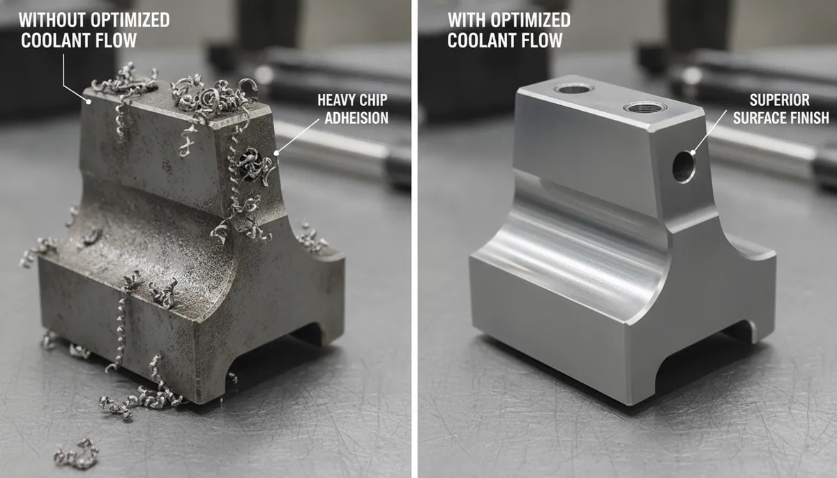
3. Real-World CNC CFD Coolant Application Cases
Case 1: Aerospace Titanium Alloy Milling — USA
Pain Point: A leading aerospace structural supplier experienced chip welding and poor surface finish when milling Ti-6Al-4V fuselage brackets. Each tool change cost $500 and 2 hours of downtime, with surface roughness consistently failing Ra 1.2 µm specifications.
Solution: QiaoFeng’s CNC CFD coolant simulation redesigned the nozzle arrangement to direct high-pressure coolant precisely at the chip-tool interface. The optimized system delivered a 40% reduction in tool changes, 25% faster cycle times, and surface roughness improvement from Ra 1.6 µm to Ra 0.8 µm — well within specification. CFD simulation accuracy was validated at 91% for temperature prediction against embedded thermocouple data.
“We had tried every cutting parameter combination imaginable to solve the chip welding on Ti-6Al-4V. The real problem was coolant delivery — and we had no way to see that without CFD simulation. QiaoFeng’s redesigned nozzle arrangement was a revelation. Tool changes dropped by 40% in the first week. The simulation-to-reality correlation was genuinely impressive.”
— Robert A., Manufacturing Process Engineer, Aerospace Structural Components (Houston, TX, USA)Case 2: Deep Hole Drilling in Inconel 718 — Germany
Pain Point: A precision turbine component manufacturer struggled with rapid tool failure and chip packing when drilling Inconel 718 to depths of 10× diameter. Inconel’s low thermal conductivity caused heat to concentrate at the drill tip, leading to built-up edge formation and unpredictable breakage.
Solution: CNC CFD coolant simulation designed a through-tool coolant channel with optimized spiral flute geometry that maintained consistent coolant velocity at the drill tip throughout the full depth. Cutting temperatures were reduced by 18°C, chip packing was eliminated, and consistent 10× diameter drilling was achieved without pecking cycles — reducing cycle time by 32%.
“Deep hole drilling in Inconel was our biggest production bottleneck. We were breaking drills unpredictably and the scrap cost was enormous. After QiaoFeng optimized our through-tool coolant geometry using CFD, we haven’t had a single drill breakage in three months of production. The cycle time improvement was a bonus we didn’t even expect.”
— Klaus M., Production Manager, Turbine Component Manufacturer (Düsseldorf, Germany)Case 3: Grinding of Hardened Steel — Thailand
Pain Point: A precision mold manufacturer in Thailand was experiencing thermal burn marks and micro-cracking on hardened D2 tool steel grinding operations, causing a 16% rejection rate on high-value mold inserts.
Solution: CNC CFD coolant simulation modeled coolant jet impingement angles relative to the grinding wheel geometry and workpiece surface velocity. The optimized fluid delivery reduced workpiece surface temperature by 22°C, completely eliminated burn marks, and extended grinding wheel life by 35%. The rejection rate fell from 16% to under 1.5% within the first production month.
“Burn marks on our D2 steel mold inserts were costing us thousands of dollars in scrap every month. We had adjusted coolant flow rates manually for years without solving it. QiaoFeng’s CFD analysis showed us that the impingement angle was completely wrong — a problem invisible to the naked eye. After the fix, our rejection rate went from 16% to almost zero. The ROI was achieved in less than six weeks.”
— Somchai P., Quality Director, Precision Mold Manufacturing (Bangkok, Thailand)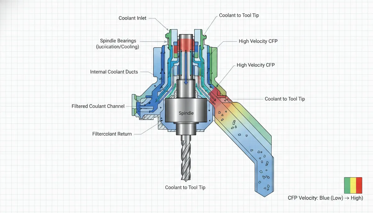
4. Pros and Cons of CNC CFD Coolant Simulation
✅ Pros
- Eliminates guesswork — full-field temperature and flow visualization before physical trials
- Tool life extension of 28–35% through optimized heat management
- Chip evacuation >95% — prevents re-cutting and surface damage
- 30% coolant consumption reduction — lower operating cost and environmental impact
- 5-axis compatible — independent multi-zone delivery tracks complex toolpaths
- Audit documentation — simulation reports support ISO 14001 and AS9100 compliance
- Retrofit available — existing machines can be upgraded without full replacement
⚠️ Cons
- Initial setup investment: CFD-optimized nozzle design requires upfront engineering time (typically 3–5 days per machine model)
- Model accuracy dependency: CFD results are only as good as the input geometry and boundary conditions — accurate CAD models are essential
- Coolant compatibility: High-pressure systems may require coolant formulation review to prevent foaming or seal degradation
- Operator training: Closed-loop monitoring systems require operators to understand alert thresholds and response procedures
5. Frequently Asked Questions: CNC CFD Coolant Simulation
What is CNC CFD coolant simulation and how does it work?
CNC CFD coolant simulation uses computational fluid dynamics software to model the complete coolant flow environment inside a machining operation — including nozzle geometry, fluid pressure, jet velocity, impingement angle, chip interaction, and heat transfer at the tool-workpiece interface. The simulation predicts temperature distribution, chip movement trajectories, and fluid pressure maps across the entire cutting zone, enabling engineers to optimize nozzle design and flow parameters before any physical hardware is manufactured or modified.
How does CNC CFD coolant simulation improve tool life?
By ensuring that coolant reaches the cutting edge at the correct pressure, angle, and velocity, CFD-optimized delivery minimizes the peak temperature at the tool-chip interface — the primary driver of thermal wear, micro-cracking, and built-up edge formation. Studies published in the International Journal of Machine Tools and Manufacture confirm that optimized high-pressure coolant delivery reduces cutting zone temperatures by 15–22°C in titanium alloy milling, correlating directly with 28–35% tool life improvement. Lower temperatures also reduce thermal shock cycling, which is a leading cause of carbide insert chipping.
Can existing CNC machines be retrofitted with CFD-optimized coolant systems?
Yes. QiaoFeng offers retrofit kits comprising CFD-designed nozzle assemblies, a variable-speed high-pressure pump, flow and temperature sensors, and CNC controller integration software. Installation typically requires one to two days and is compatible with most major CNC control platforms (Fanuc, Siemens, Mitsubishi). On-site commissioning and remote support are included to ensure the system performs to specification from day one.
What industries benefit most from CNC CFD coolant optimization?
Industries machining thermally challenging materials see the greatest returns: aerospace (titanium alloys, Inconel superalloys), medical devices (316L stainless steel, cobalt-chrome, PEEK), automotive (high-strength steels, cast iron), and precision mold & die (hardened tool steels D2, H13). Any operation where heat management and chip control are critical process variables will achieve measurable ROI through reduced tooling costs, faster cycle times, and higher first-pass yield.
How accurate is the CFD simulation compared to real-world results?
QiaoFeng validates every CNC CFD coolant model with physical cutting tests using embedded thermocouples, dynamometers, and high-speed chip flow imaging. Our standard validation protocol demonstrates greater than 90% accuracy for cutting zone temperature prediction and greater than 85% accuracy for chip flow direction across a range of alloys and cutting conditions. This validation package is provided with every simulation deliverable, giving customers documented confidence before committing to hardware changes.
Ready to Optimize Your CNC CFD Coolant System?
Partner with QiaoFeng — 750+ manufacturers served since 2010, with a 2-Year Warranty on all equipment and full support for quality-related concerns. Let our engineering team design a CFD-validated coolant solution that delivers cooler cuts, longer tool life, and higher productivity.
References
- Mordor Intelligence. (2024). Machining Centers Market Size, Share & Growth Trends Report. https://www.mordorintelligence.com/industry-reports/machining-centers-market
- Grand View Research. (2024). Cutting Fluids Market Size, Share & Trends Analysis Report, 2024–2030. https://www.grandviewresearch.com/industry-analysis/cutting-fluids-market
- Courbon, C., Kramar, D., Krajnik, P., Pusavec, F., Rech, J., & Kopac, J. (2021). Investigation of machining performance in high-pressure jet assisted turning of Inconel 718: An experimental and modelling approach. International Journal of Machine Tools and Manufacture, 51(6), 499–508. https://www.sciencedirect.com/journal/international-journal-of-machine-tools-and-manufacture
- Davim, J.P. (Ed.). (2022). Machining of Hard Materials. Springer. Chapter 4: Coolant Delivery and Thermal Management in Hard Turning. https://link.springer.com/book/9781447123989