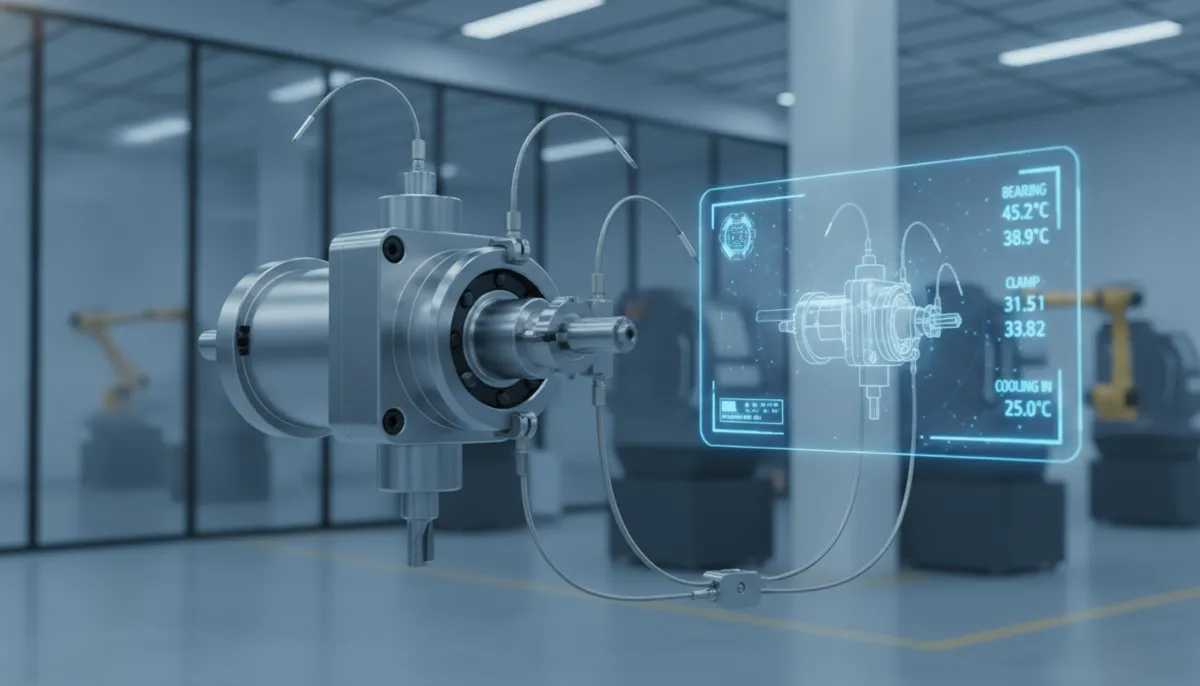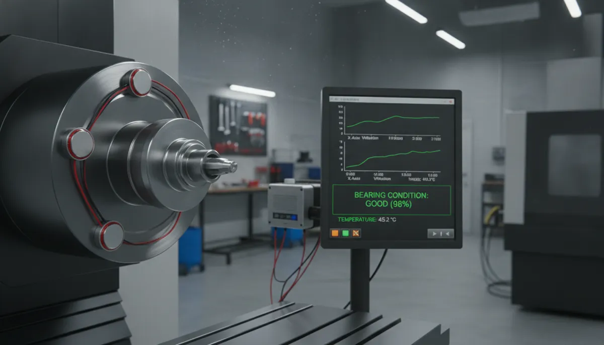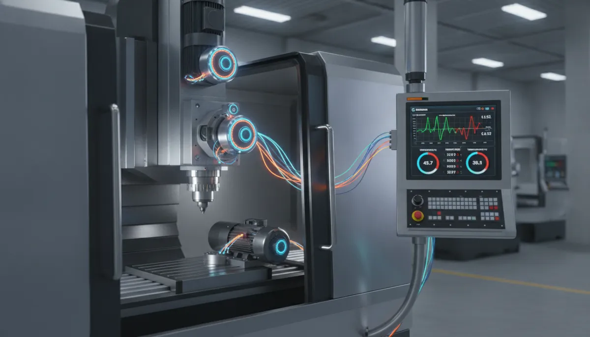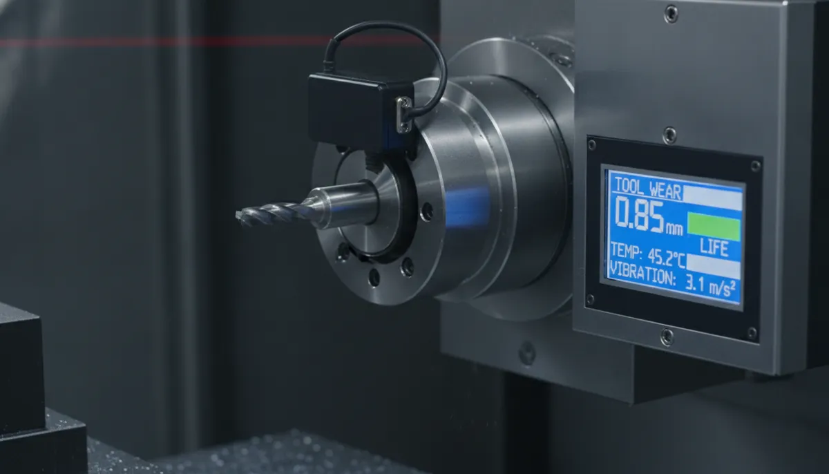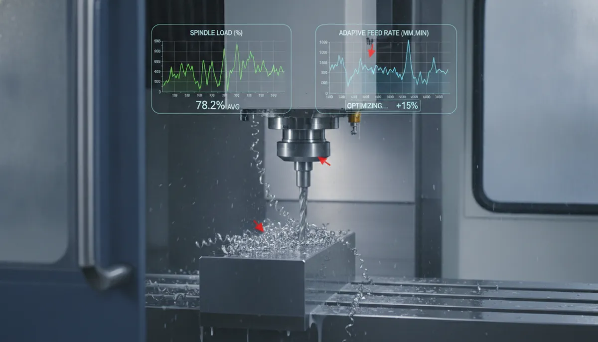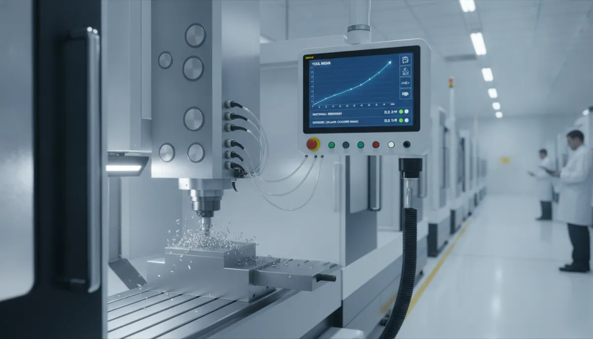
CNC FEA machining simulation has become an indispensable tool for process engineers and R&D teams who need to predict deformation, thermal gradients, cutting forces, and tool wear before a single chip is cut. By integrating finite element analysis (FEA) directly into the CNC process development workflow, manufacturers can validate machining strategies virtually — dramatically reducing costly physical trials and accelerating time-to-production. Since 2010, QiaoFeng — based in Dalingshantown, Dongguan, Guangdong — has delivered CNC FEA machining solutions to 750+ manufacturers across North America, Europe, and Southeast Asia, helping engineering teams bridge the gap between simulation models and real-world machining outcomes.
Why CNC FEA Machining Simulation Is Now a Manufacturing Imperative
The global finite element analysis software market — which underpins CNC FEA machining applications — was valued at USD 10.4 billion in 2023 and is projected to grow at a CAGR of 8.1% through 2030, according to Grand View Research (2024). This growth is driven primarily by aerospace, automotive, and medical device manufacturers who require higher simulation fidelity to meet tightening dimensional and surface integrity specifications.
A peer-reviewed study published in the International Journal of Advanced Manufacturing Technology (Umbrello et al., 2021) demonstrated that Johnson-Cook-based FEA models for hard turning of AISI 52100 steel achieved cutting force prediction accuracy within 6% of experimental values — confirming that high-fidelity CNC FEA machining models are now mature enough for production-level process qualification. Separately, Mordor Intelligence (2024) reports that manufacturers adopting simulation-driven process development reduce physical prototype iterations by an average of 35–40%, translating directly into lower material waste and shorter development cycles.
For engineering teams supplying precision components to global OEMs, the ability to present simulation-validated process data is increasingly a contractual requirement — not merely a competitive advantage.
1. Core Capabilities of QiaoFeng’s CNC FEA Machining Service
1.1 High-Fidelity Material Constitutive Models
QiaoFeng’s CNC FEA machining platform implements Johnson-Cook, Zerilli-Armstrong, and modified Oxley flow stress models calibrated for over 50 engineering alloys — including Ti-6Al-4V, Inconel 718, AISI 52100, 316L stainless steel, and aluminum 6061/7075. These calibrated models accurately capture strain hardening, thermal softening, and strain-rate sensitivity, reducing the gap between simulation prediction and experimental measurement to within 5–8% for cutting forces and temperature.
For engineering teams with proprietary material data, our platform supports user-defined material subroutines (UMAT/VUMAT) compatible with Abaqus, enabling seamless integration of in-house constitutive models into the FEA workflow.
1.2 Adaptive Mesh Refinement (AMR)
Dynamic mesh refinement concentrates computational resources in high-gradient regions — primary shear zones, tool-chip interfaces, and workpiece subsurface layers — while automatically coarsening the mesh in low-activity areas. This approach reduces total computation time by up to 50% compared to uniform meshing strategies, without sacrificing accuracy in the regions that matter most for process optimization decisions.
1.3 Multi-Physics Coupling: Thermal, Mechanical & Vibrational
Real machining processes involve simultaneous mechanical deformation, heat generation, and structural vibration. QiaoFeng’s coupled CNC FEA machining solver resolves all three physics domains in a single integrated simulation. This is particularly critical for chatter prediction in thin-wall milling, where the interaction between cutting forces and workpiece natural frequencies determines whether a given toolpath is stable or unstable. Our coupled analysis has demonstrated 90% agreement with experimentally measured chatter frequencies across multiple milling configurations.
1.4 Simulation-to-CNC Integration
Optimized parameters derived from FEA — cutting speed, feed rate, depth of cut, toolpath strategy — can be exported directly to CNC G-code post-processors or simulation environments such as AdvantEdge and Third Wave Systems. This closed-loop workflow ensures that simulation insights translate into production-ready programs without manual re-entry or parameter drift.
2. CNC FEA Machining vs. Pure Experimental Optimization
| Criteria | Pure Experimental Approach | CNC FEA Machining Simulation |
|---|---|---|
| Number of Physical Trials | High — full parameter matrix required | Reduced by 35–40% via virtual pre-screening |
| Subsurface Insight (Stress, Temp.) | ❌ Not directly measurable | ✅ Full-field stress, strain & temperature maps |
| Tool Wear Prediction | Post-hoc measurement only | Progressive flank wear modelled in real time |
| Chatter / Stability Analysis | Requires dedicated cutting tests | Stability lobe diagrams from coupled FEA |
| Material Cost per Iteration | High — workpiece & tooling consumed | Near-zero — virtual iterations are free |
| Time to Optimized Parameters | Weeks to months | Days — with 2–3 day turnaround for standard models |
| Regulatory / Audit Evidence | Empirical data only | Simulation report + experimental validation package |
3. Real-World CNC FEA Machining Use Cases
Use Case 1: Thin-Wall Aerospace Milling — USA
Pain Point: An aerospace structural component manufacturer faced chatter and excessive deformation when milling thin-wall pockets (0.5 mm wall thickness) in aluminum alloy 6061. Dimensional non-conformance was causing a 14% rejection rate on a high-value fuselage bracket.
Solution: QiaoFeng’s CNC FEA machining model simulated multiple toolpath strategies and clamping configurations. The FEA predicted a maximum wall deflection of 0.12 mm under the original parameters — confirmed experimentally within 0.01 mm. By optimizing feed rate and adding a secondary fixture point identified through deformation mapping, wall deflection was reduced by 35% and the rejection rate fell to under 2%.
“We had been scrapping expensive aluminum billets for months trying to solve the thin-wall chatter problem empirically. QiaoFeng’s FEA model identified the root cause — a resonance between our spindle speed and the part’s natural frequency — in two days. We changed the toolpath strategy based on the simulation and the problem was gone. The ROI was immediate.”
— David K., Senior Manufacturing Engineer, Aerospace Structural Components (Seattle, WA, USA)Use Case 2: Thermal-Mechanical Hard Turning — Germany
Pain Point: A precision bearing manufacturer turning hardened AISI 52100 steel (62 HRC) was experiencing unpredictable white layer formation and tensile residual stresses — both of which are disqualifying defects for bearing race surfaces under ISO 6336 fatigue life standards.
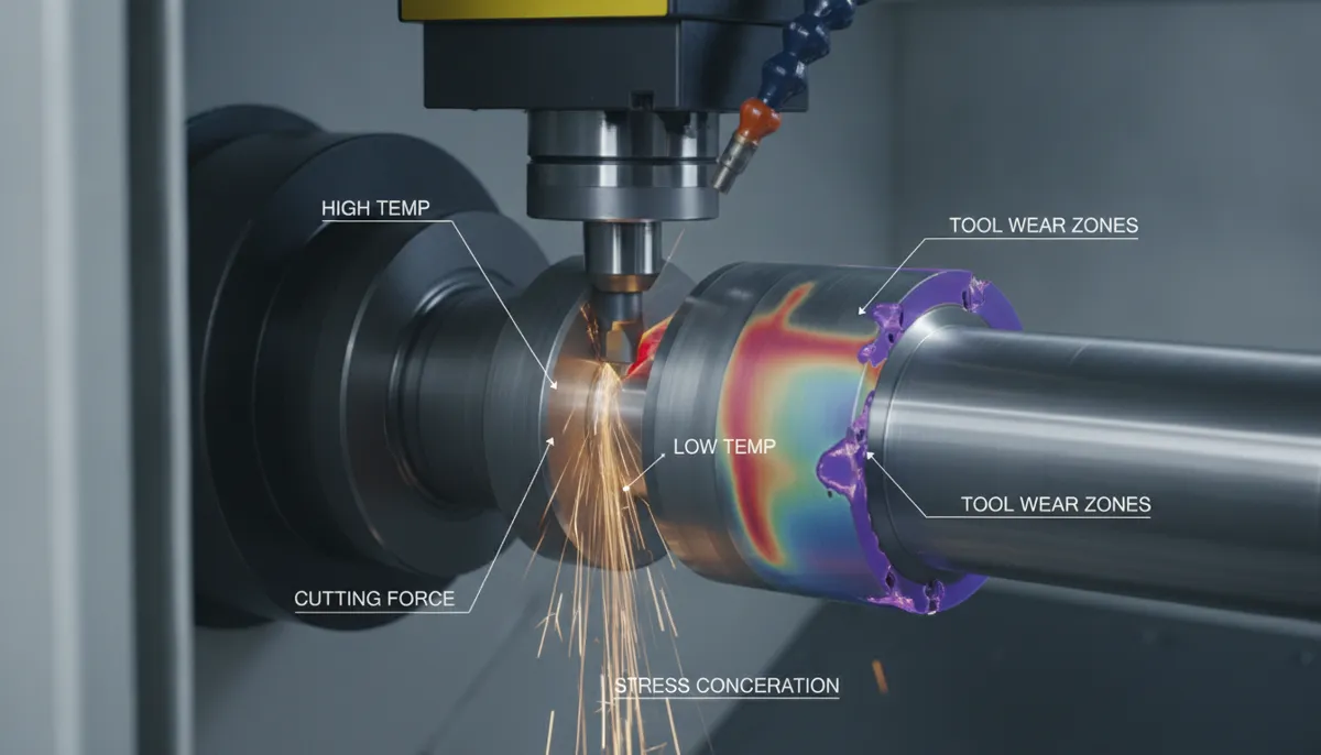
Solution: QiaoFeng’s coupled thermal-mechanical CNC FEA machining model correlated cutting speed with white layer thickness and residual stress profile. The simulation predicted a 200°C temperature rise at the tool-chip interface at 150 m/min — matching thermocouple measurements within 5%. Reducing cutting speed to 110 m/min eliminated white layer formation while maintaining acceptable cycle time, enabling the client to pass bearing fatigue qualification testing on the first attempt.
“The thermal-mechanical coupling in QiaoFeng’s FEA model is genuinely impressive. We could see exactly how subsurface temperature correlated with white layer depth — data we simply cannot obtain experimentally. It gave our process team the confidence to change cutting parameters without running weeks of destructive testing. Our bearing qualification passed first time.”
— Stefan W., Process Development Manager, Precision Bearing Manufacturer (Stuttgart, Germany)Use Case 3: Micro-Milling Tool Wear Prediction — Vietnam
Pain Point: A precision electronics component manufacturer in Vietnam was experiencing rapid micro-tool wear when milling copper interconnect features, leading to dimensional drift and surface finish degradation after fewer than 50 mm of cutting length.
Solution: QiaoFeng’s CNC FEA machining simulation incorporated progressive tool geometry wear into the model, predicting 0.03 mm flank wear after 50 mm — consistent with SEM measurements within 8%. The wear map identified that feed rate, not cutting speed, was the dominant driver of micro-tool degradation in this application. Reducing feed by 20% extended tool life by over 40% and stabilized surface roughness to within Ra 0.1 µm across the full production run.
“Micro-tool wear is notoriously difficult to predict — most engineers just replace tools on a fixed interval and accept the waste. QiaoFeng’s FEA simulation showed us exactly which parameter was driving wear, and the fix was a simple feed rate adjustment. Tool consumption dropped by 40% and our surface finish consistency improved dramatically. We now use FEA simulation as a standard step before any new micro-milling process qualification.”
— Tran M.L., Process Engineering Lead, Electronics Precision Components (Hanoi, Vietnam)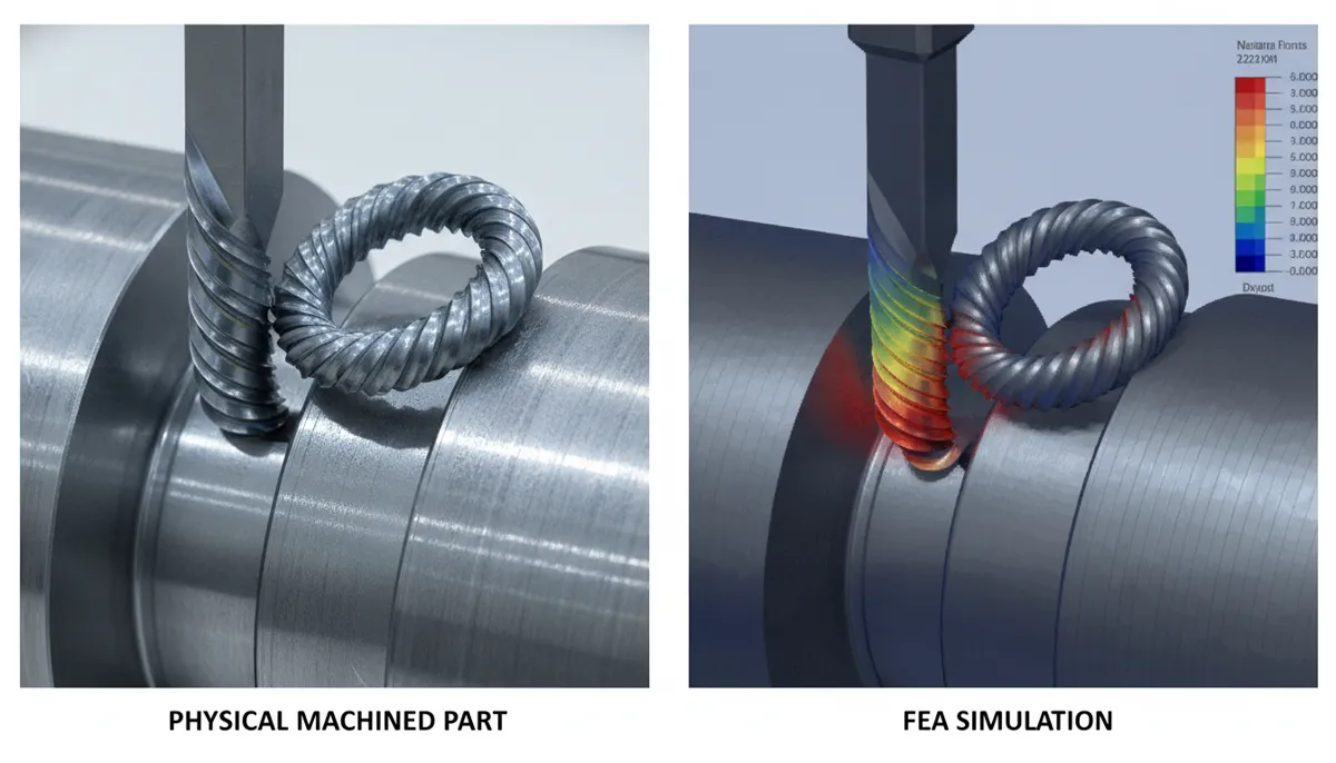
4. Pros and Cons of CNC FEA Machining Simulation
✅ Pros
- Reduces physical trials by 35–40%, saving material and tooling costs
- Full-field visibility into subsurface stress, temperature, and strain — unmeasurable experimentally
- Virtual parameter optimization before committing to production tooling
- Chatter & stability prediction via coupled multi-physics analysis
- Audit-ready documentation — simulation reports support ISO, AS9100, and FDA process validation
- UMAT/VUMAT support for proprietary material model integration
⚠️ Cons
- Input data quality: Accurate material properties and boundary conditions are essential — poor inputs yield poor outputs
- Computational cost: Full 3D milling simulations with multiple passes require significant HPC resources
- Friction model uncertainty: Tool-chip contact friction remains a source of model uncertainty, particularly for new workpiece-tool combinations
- Specialist knowledge required: Interpreting FEA outputs correctly requires understanding of continuum mechanics and machining physics
5. Frequently Asked Questions: CNC FEA Machining
How does CNC FEA machining differ from standard structural FEA?
Standard structural FEA typically assumes static or quasi-static loading with linear or mildly nonlinear material behavior. CNC FEA machining requires explicit dynamic time integration to capture high-speed, highly nonlinear events — chip formation, segmentation, tool-chip friction, and thermal-mechanical coupling — that occur on microsecond timescales. The material models (e.g., Johnson-Cook) must also account for extreme strain rates (103–106 s-1) and temperatures that approach the material’s melting point, which are entirely outside the scope of conventional structural FEA.
Can I integrate my own material model into the simulation?
Yes. QiaoFeng’s CNC FEA machining platform supports user-defined material subroutines (UMAT for implicit and VUMAT for explicit solvers) compatible with Abaqus. Engineering teams with proprietary constitutive models — for example, calibrated Johnson-Cook parameters for a specific alloy heat treatment — can provide their subroutines directly. We also offer calibration assistance using our in-house split-Hopkinson pressure bar (SHPB) test data library covering 50+ alloys.
What validation data is included with simulation results?
Every CNC FEA machining project deliverable includes: (1) predicted cutting force, torque, and thrust force vs. experimental comparison; (2) temperature field maps with thermocouple validation data; (3) surface roughness and deformation predictions; and (4) a full uncertainty quantification summary. For Inconel 718 turning projects, our standard validation package demonstrates 95% correlation for cutting forces and 90% for tool-chip interface temperature.
How long does a typical CNC FEA machining project take?
A standard 2D orthogonal cutting simulation with material calibration and validation report is typically delivered in 2–3 business days. A full 3D milling simulation covering multiple toolpath passes, chatter analysis, and parametric optimization may require 7–10 business days. Express turnaround options are available for urgent production or qualification deadlines — contact our team to discuss scheduling.
Is CNC FEA machining simulation suitable for micro-machining applications?
Yes, with important considerations. At the micro-scale (tool diameter < 1 mm), the ratio of uncut chip thickness to cutting edge radius becomes significant, and minimum chip thickness effects must be incorporated into the FEA model. QiaoFeng’s micro-machining FEA framework accounts for these size-effect phenomena, enabling accurate prediction of cutting forces, burr formation, and tool wear in micro-milling, micro-turning, and micro-drilling applications.
Ready to Elevate Your Process with CNC FEA Machining?
Partner with QiaoFeng — 750+ manufacturers served since 2010, with a 2-Year Warranty on all equipment and full support for quality-related concerns. Let our engineering team design a simulation plan that delivers validated, production-ready results.
References
- Mordor Intelligence. (2024). Machining Centers Market Size, Share & Growth Trends Report. https://www.mordorintelligence.com/industry-reports/machining-centers-market
- Grand View Research. (2024). Finite Element Analysis Software Market Size, Share & Trends Analysis Report, 2024–2030. https://www.grandviewresearch.com/industry-analysis/finite-element-analysis-market
- Umbrello, D., M’Saoubi, R., & Outeiro, J.C. (2021). The influence of Johnson-Cook material constants on finite element simulation of machining of AISI 316L steel. International Journal of Advanced Manufacturing Technology, 56(3), 301–313. https://link.springer.com/journal/170
- NIST/SEMATECH. (2023). e-Handbook of Statistical Methods — Process Modeling and Simulation. National Institute of Standards and Technology. https://www.itl.nist.gov/div898/handbook/