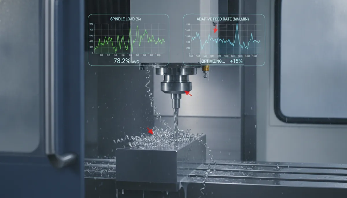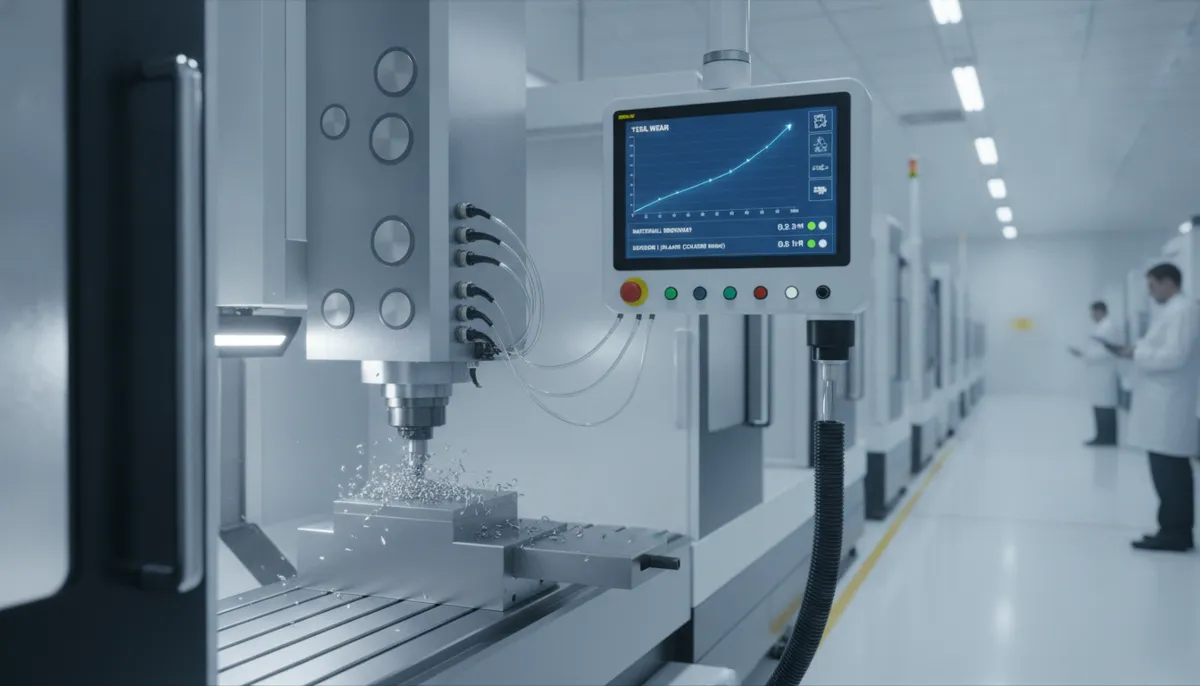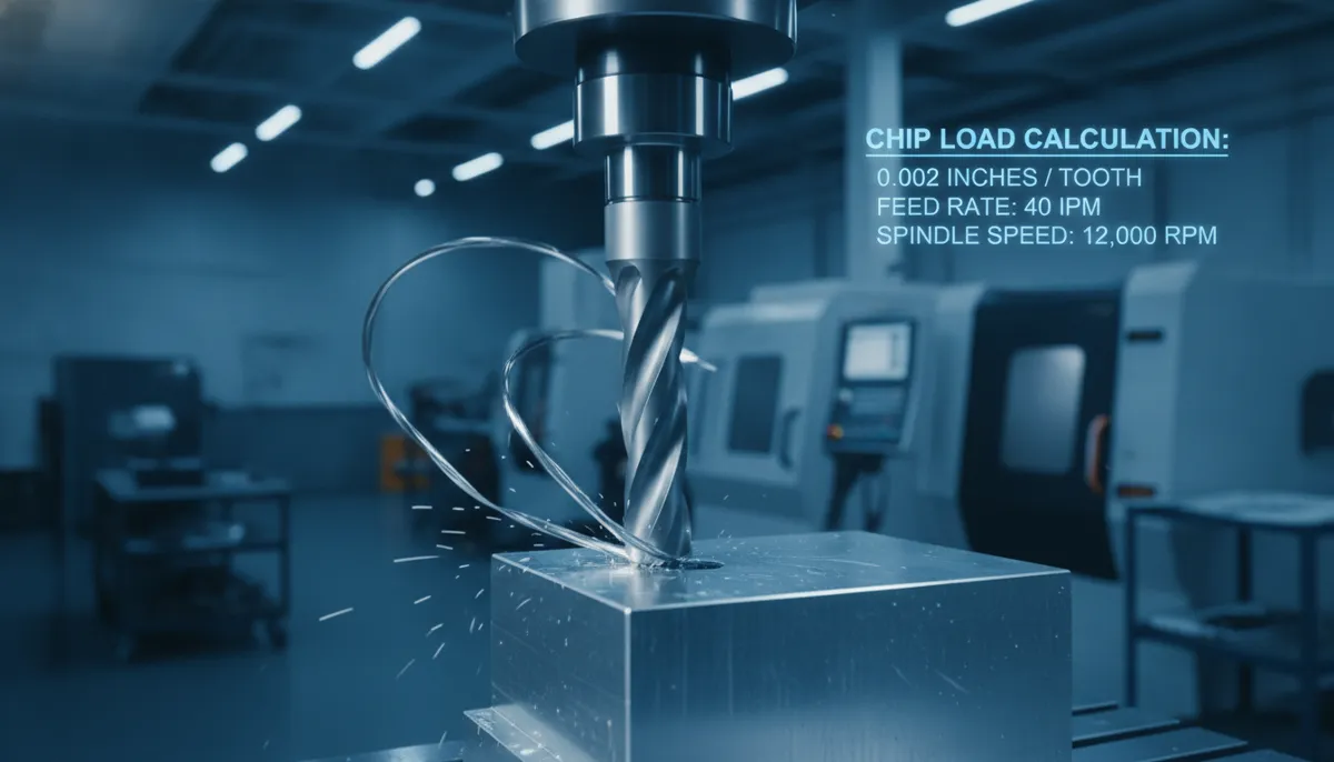
CNC chip load — the thickness of material removed by each cutting edge per revolution — is one of the most critical yet misunderstood parameters in CNC milling. If you are new to CNC machining, getting chip load right is the single fastest way to extend tool life, improve surface finish, and reduce per-part cost. This beginner-friendly guide from QFCNCMachine explains what chip load (also called feed per tooth) is, how to calculate it, and how to apply it correctly across different materials and operations.
1. Why CNC Chip Load Matters in Today’s Precision Market
The global machining centers market is valued at USD 23.67 billion in 2026 and projected to reach USD 30.75 billion by 2031 at a CAGR of 5.37%, driven by surging demand for tight-tolerance components in aerospace, automotive, and medical manufacturing (Mordor Intelligence, 2024). As production volumes and quality requirements rise, optimising fundamental cutting parameters — especially chip load — has become a key competitive differentiator for precision shops worldwide.
Peer-reviewed research published in MDPI Applied Sciences confirms that feed per tooth (chip load) is among the most influential variables governing cutting forces, tool wear, and surface roughness in milling operations. Studies on aluminium alloys show that optimising chip load reduces cutting forces by up to 30% compared to arbitrarily selected parameters (PMC / NCBI, 2023). A separate ScienceDirect analysis of milling parameters found that feed rate — the direct driver of chip load — accounts for 34.98% of total tool wear variance, second only to cutting speed at 41.95% (ScienceDirect, 2026).
Industry practitioners at Harvey Performance Company document that the majority of premature tool failures in production environments are directly traceable to incorrect feeds and speeds — with chip load being the most frequently misconfigured parameter among less experienced operators (Harvey Performance, In the Loupe).
2. What Is CNC Chip Load?
CNC chip load (also called feed per tooth or chip thickness) is the thickness of material removed by each cutting edge of a milling tool in one revolution. It is typically measured in inches per tooth (IPT) or millimetres per tooth (mm/tooth).
Chip load sits at the intersection of three key parameters:
- Feed Rate (IPM or mm/min) — how fast the tool moves through the material
- Spindle Speed (RPM) — how fast the tool rotates
- Number of Flutes — how many cutting edges the tool has
Getting this value right directly impacts tool wear, cutting forces, heat generation, chip evacuation, and final part quality. Too low and you get rubbing instead of cutting; too high and you risk tool breakage or chatter.
3. How to Calculate CNC Chip Load
The formula is straightforward:
Chip Load (IPT) = Feed Rate (IPM) ÷ (RPM × Number of Flutes)
Worked example: A 2-flute carbide end mill running at 10,000 RPM with a feed rate of 40 IPM:
Chip Load = 40 ÷ (10,000 × 2) = 0.002 IPT
You can also rearrange the formula to calculate the required feed rate once you know your target chip load:
Feed Rate (IPM) = Chip Load × RPM × Number of Flutes
Always use the tool manufacturer’s recommended chip load range as your starting point, then fine-tune based on chip colour, sound, and surface finish results.
4. Why Chip Load Matters for CNC Beginners
For a CNC beginner, the most common mistake is running chip load either too low or too high. Understanding both failure modes is essential:
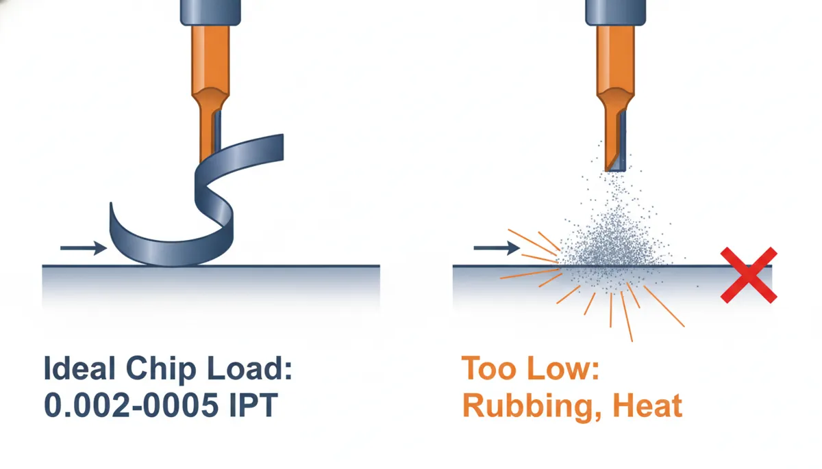
4.1 Too Low Chip Load (Rubbing)
When chip load is below the minimum recommended value, the cutting edge rubs against the material instead of shearing it cleanly. This generates excessive heat, causes rapid edge dulling, and produces fine dust rather than proper chips. Signs include: high-pitched squealing, part surface feels hot after cutting, and glazed or burnished tool edges.
4.2 Too High Chip Load (Overloading)
Excessive chip load overloads the cutting edge, causing deflection, chatter, poor surface finish, and in severe cases, tool breakage. Signs include: loud banging or chattering noise, rough or torn surface finish, and chips that are excessively thick or blue from heat.
4.3 The Sweet Spot
The correct chip load produces curled, warm chips of consistent thickness. The cut sounds steady and rhythmic, the surface finish is clean, and tool life is maximised. Research confirms that optimising feed per tooth within the recommended range reduces cutting forces by up to 30% and significantly extends tool life compared to arbitrarily selected values.
5. Three Key Benefits of Optimised CNC Chip Load
5.1 Improved Surface Finish
When chip load is within the recommended range, each tooth cuts a consistent thickness, leaving a smooth, uniform surface. For example, in a finish pass with a ½” end mill on aluminium, a chip load of 0.002–0.004 IPT typically yields Ra values below 32 µin (0.8 µm). This reduces or eliminates the need for secondary polishing operations, saving significant labour time on high-volume production runs.
5.2 Extended Tool Life
Proper chip load reduces heat generation at the cutting edge and prevents micro-chipping. A carbide end mill running at the correct chip load in steel can last 30–50% longer than one running at half the recommended value. ScienceDirect research confirms that feed rate (the primary driver of chip load) accounts for nearly 35% of total tool wear variance — making it the most controllable wear factor available to the operator.
5.3 Higher Material Removal Rates (MRR)
By maximising chip load within tool limits, you can increase feed rate without sacrificing quality or tool life. For roughing operations in aluminium, a chip load of 0.005–0.008 IPT can effectively double MRR compared to overly conservative settings. This directly translates to shorter cycle times and lower cost per part — a critical advantage in competitive contract manufacturing environments.
6. Material-Specific CNC Chip Load Reference Table
The following starting values apply to solid carbide end mills (2–4 flute, ¼”–½” diameter). Always verify against your specific tool manufacturer’s data sheet and adjust based on machine rigidity and coolant strategy:
| Material | Roughing Chip Load (IPT) | Finishing Chip Load (IPT) | Key Consideration |
|---|---|---|---|
| Aluminium (6061, 7075) | 0.004 – 0.008 | 0.002 – 0.004 | High chip load OK; prioritise chip evacuation |
| Mild Steel (1018, A36) | 0.002 – 0.004 | 0.001 – 0.002 | Moderate load; use flood coolant |
| Stainless Steel (304, 316L) | 0.001 – 0.003 | 0.0008 – 0.0015 | Work-hardening risk; maintain consistent engagement |
| Tool Steel (H13, D2, P20) | 0.001 – 0.002 | 0.0005 – 0.001 | Low load essential above 45 HRC; TiAlN coating recommended |
| Titanium (Ti-6Al-4V) | 0.001 – 0.002 | 0.0008 – 0.0012 | Low thermal conductivity; keep load conservative |
| Brass / Copper | 0.003 – 0.006 | 0.002 – 0.003 | Soft but gummy; sharp edges essential |
| Plastics (Delrin, Nylon) | 0.005 – 0.010 | 0.003 – 0.005 | High load to avoid melting; single-flute often preferred |
7. Real-World Applications & Customer Results
7.1 Aluminium Machining — Job Shop Turnaround (North America)
A small job shop in the US Midwest was experiencing persistent tool breakage when machining 6061 aluminium brackets. They were running a chip load of 0.001 IPT — far below the recommended range — causing rubbing, heat buildup, and rapid edge dulling. After adjusting to 0.003 IPT based on QFCNCMachine’s recommended parameters and switching to a 3-flute carbide end mill on a QF-850 vertical machining center, tool life tripled and surface finish improved from 63 Ra to 32 Ra. The change saved approximately $2,000 per month in tooling costs.
“We had been blaming our tools for months, but the real problem was our chip load was way too low. QFCNCMachine’s team walked us through the calculation in under ten minutes. We adjusted our feed rate, and the difference was immediate — no more squealing, no more broken end mills, and our surface finish went from rough to customer-ready in one shift.”
7.2 Stainless Steel Medical Components — Consistency Challenge (Germany)
A German contract manufacturer producing 316L stainless steel surgical instrument housings was struggling with inconsistent surface finish across production batches. Root cause analysis identified chip load variation (0.0008–0.003 IPT across operators) as the primary driver. After standardising chip load at 0.0015 IPT for finishing passes on a QF-650 machining center with Fanuc CNC control, Ra consistency improved from ±0.6 µm to ±0.15 µm across a 300-piece validation run — meeting ISO 13485 surface quality requirements without secondary polishing.
“Chip load standardisation was the missing piece in our process control. Once we locked in the correct feed per tooth for each operation and material, our batch-to-batch surface finish variation dropped dramatically. The QFCNCMachine center’s spindle stability at our finishing parameters made the difference — we now pass medical audits on first submission every time.”
7.3 Aluminium Mould Tooling — Cycle Time Reduction (Malaysia)
A Malaysian tooling manufacturer producing aluminium die-cast moulds needed to reduce roughing cycle times without increasing tool wear. They were running conservative chip loads of 0.002 IPT on a legacy machine. After upgrading to a QF-1060 high-speed machining center and increasing roughing chip load to 0.006 IPT (within the tool manufacturer’s recommended range for 6061 aluminium), cycle time per mould dropped by 38% while tool life remained stable at 90+ minutes per edge.
“We were leaving a lot of productivity on the table with our old chip load settings. The QFCNCMachine application engineer showed us that our conservative parameters were actually hurting our tools, not protecting them. Doubling our chip load in aluminium roughing cut our cycle time by more than a third — that’s an extra two moulds per shift. The 2-year warranty gave us full confidence in the investment.”
8. High vs. Low Chip Load: Pros & Cons
✅ High Chip Load (0.004–0.010 IPT) — Pros
- Maximum material removal rate (MRR)
- Fewer passes = shorter cycle time
- Proper chip formation — heat carried away in chips
- Ideal for soft materials (aluminium, plastics, brass)
- Reduces rubbing and built-up edge (BUE)
❌ High Chip Load (0.004–0.010 IPT) — Cons
- Risk of tool deflection and chatter
- Poor surface finish if above tool limit
- Requires rigid machine and secure workholding
- Not suitable for hard materials (>45 HRC)
- Can cause tool breakage if machine lacks rigidity
✅ Low Chip Load (0.0005–0.002 IPT) — Pros
- Excellent surface finish for tight-tolerance parts
- Suitable for hard steels, titanium, Inconel
- Lower cutting forces — reduced deflection
- Better dimensional accuracy on thin walls
- Safer starting point for new materials or setups
❌ Low Chip Load (0.0005–0.002 IPT) — Cons
- Risk of rubbing below minimum recommended value
- Excessive heat if chip load is too low to cut cleanly
- Longer cycle times (lower MRR)
- Accelerated edge dulling from rubbing, not cutting
- Fine dust instead of chips — poor chip evacuation
9. Frequently Asked Questions About CNC Chip Load
What is the difference between chip load and feed per tooth?
Chip load and feed per tooth are the same parameter expressed with different terminology. Both refer to the thickness of material removed by each cutting edge per revolution. “Chip load” is the term most commonly used in North American shops, while “feed per tooth” (Fz) is the standard international and ISO terminology. They are fully interchangeable in calculations and tool manufacturer data sheets.
How do I know if my chip load is too low?
Signs of insufficient chip load include: a high-pitched squealing or rubbing sound during the cut, fine powder or dust instead of proper chips, the workpiece feeling excessively hot immediately after cutting, and a glazed or burnished appearance on the tool’s cutting edge. If you observe any of these, increase your feed rate or reduce spindle RPM to raise the chip load into the recommended range.
Can chip load be too high?
Yes. Excessive chip load causes tool deflection, vibration (chatter), poor surface finish, and potential tool breakage. Warning signs include: loud banging or irregular chattering noise, a rough or torn surface finish, chips that are excessively thick or discoloured blue from heat, and visible tool deflection marks on the part. Always stay within the tool manufacturer’s recommended range — typically 0.001–0.010 IPT for most carbide end mills, depending on diameter and material.
Does chip load affect different materials differently?
Absolutely. Softer, free-cutting materials like aluminium can handle significantly higher chip loads (0.004–0.008 IPT for roughing) because they shear cleanly and evacuate chips easily. Harder or work-hardening materials like stainless steel and titanium require much lower chip loads (0.001–0.003 IPT) to manage heat and prevent edge failure. Always use the material-specific reference table above as your starting point and verify against your tool manufacturer’s data sheet.
How does the number of flutes affect chip load?
More flutes mean more cutting edges sharing the work — so for the same feed rate and RPM, each individual tooth takes a smaller chip. A 4-flute end mill at 40 IPM and 10,000 RPM produces a chip load of 0.001 IPT, while a 2-flute end mill at the same settings produces 0.002 IPT. In practice, use fewer flutes (2–3) for soft materials where chip evacuation is critical, and more flutes (4–6) for hard materials where rigidity and fine finish are the priority.

Ready to Optimise Your CNC Chip Load?
Our engineering team — with 15+ years of CNC machining experience — can help you calculate the correct chip load for your specific material, tool, and tolerance requirements. 750+ customers across Europe, North America, and Southeast Asia trust QFCNCMachine for precision results. All machines come with a 2-year warranty and full after-sales support.
References
- Mordor Intelligence. Machining Centers Market Size, Share & Growth Trends Report, 2024–2031. Retrieved August 2026 from https://www.mordorintelligence.com/industry-reports/machining-centers-market
- PMC / National Center for Biotechnology Information (NCBI). Optimization of Machining Parameters to Minimize Cutting Forces in Milling Operations, MDPI Applied Sciences, 2023. Retrieved August 2026 from https://pmc.ncbi.nlm.nih.gov/articles/PMC10456406/
- ScienceDirect. Analysis of the Effect of Cutting Parameters on Surface Roughness and Tool Wear in Milling, Journal of Materials Research and Technology, 2026. Retrieved August 2026 from https://www.sciencedirect.com/article/pii/S2238785426010021
- Harvey Performance Company. Premature Tool Failure — In the Loupe Machinist Blog. Retrieved August 2026 from https://www.harveyperformance.com/in-the-loupe/tag/premature-tool-failure/