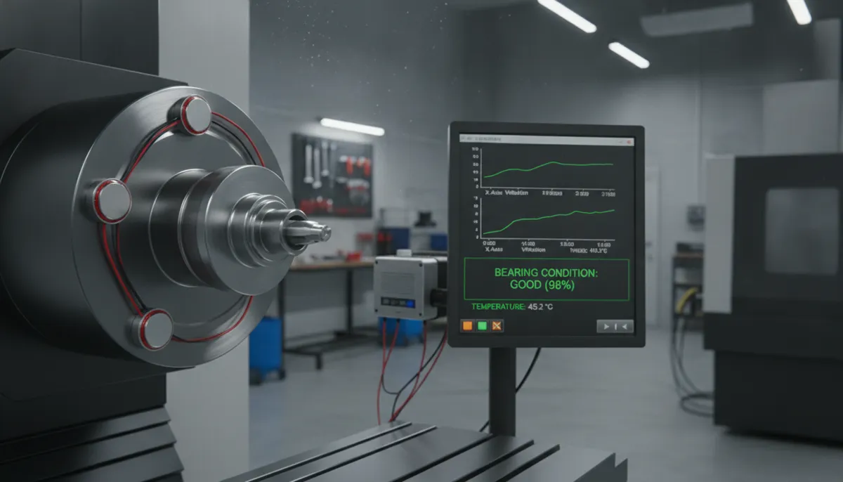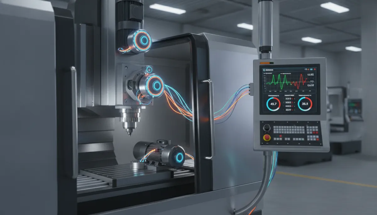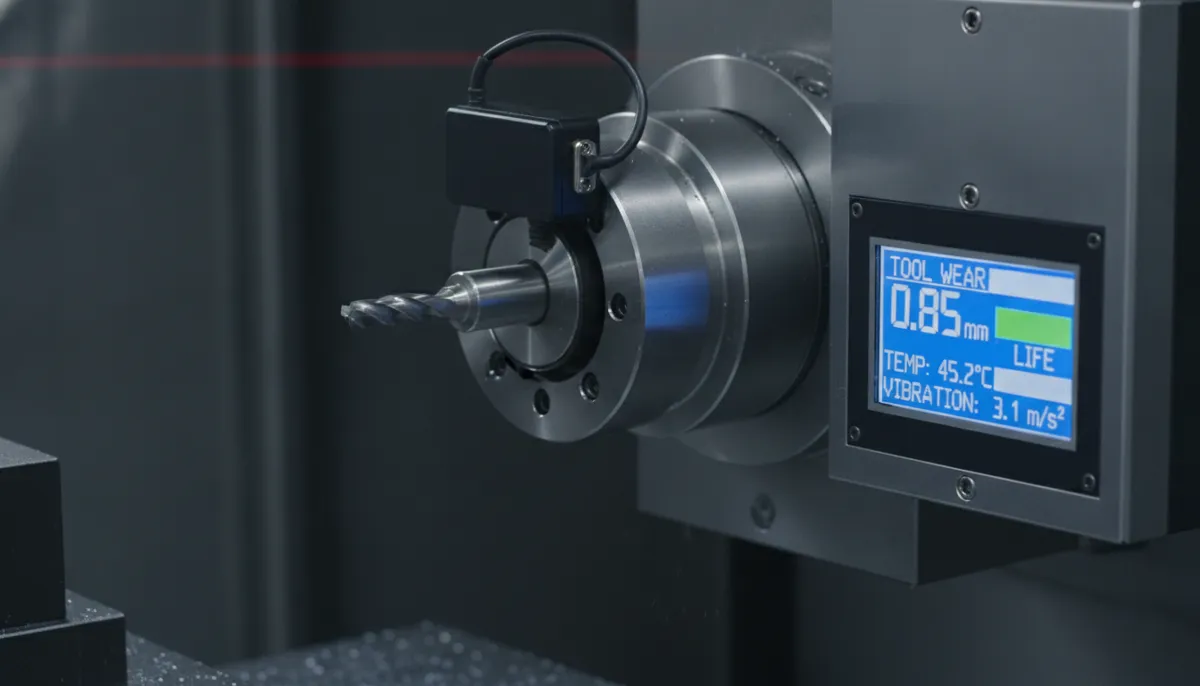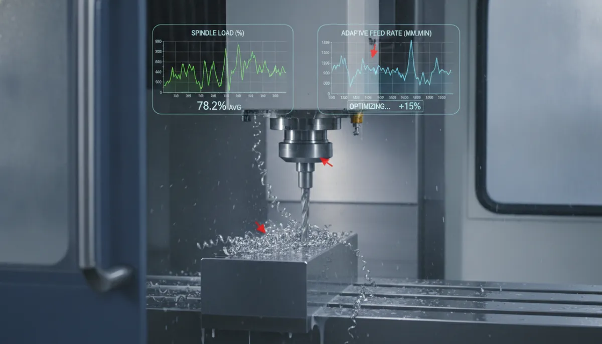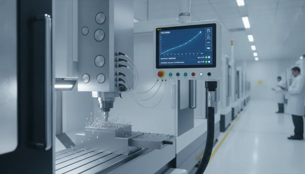
CNC stepover — the lateral distance a cutting tool moves between successive passes — is one of the most consequential parameters in modern CNC milling. Set it too wide and you sacrifice surface quality; set it too narrow and cycle times balloon. Whether you are roughing aerospace titanium brackets or finishing medical-grade implants, mastering CNC stepover is the single fastest way to improve part quality, extend tool life, and reduce per-part cost. This guide explains what stepover is, how to calculate it, and how to choose the right value for every material and application.
1. Why CNC Stepover Matters in Today’s Precision Market
The global machining centers market is valued at USD 23.67 billion in 2026 and is forecast to reach USD 30.75 billion by 2031 at a CAGR of 5.37%, driven by rising demand for tight-tolerance components in aerospace, automotive, and medical sectors (Mordor Intelligence, 2024). As part complexity increases, optimizing milling parameters — especially stepover — has become a competitive differentiator.
Research published in Procedia CIRP confirms that radial engagement (the basis of stepover) directly governs chip thickness, cutting forces, and thermal load on the tool edge. Studies on solid carbide end mills show that increasing material removal rate (MRR) through aggressive radial engagement accelerates tool degradation in both steel and aluminium alloys (ScienceDirect, 2025). Conversely, high-efficiency milling (HEM) strategies that reduce radial engagement to 10–15% of tool diameter while increasing axial depth have been shown to cut roughing cycle times by up to 35% without sacrificing tool life (CloudNC, 2024).
SME’s Manufacturing Engineering magazine (September 2023) highlights that CNC parameter optimisation — including stepover, feed rate, and depth of cut — remains the top lever for shops seeking to improve throughput without capital investment (SME, 2023).
2. What Is CNC Stepover?
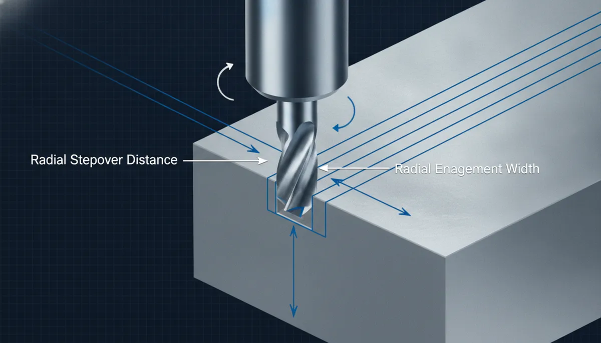
CNC stepover (also called radial engagement or radial depth of cut) defines how far the cutter steps sideways between each milling pass. It is typically expressed as a percentage of the tool diameter:
Stepover (%) = (Radial Engagement ÷ Tool Diameter) × 100
For example, a 10 mm end mill with a 4 mm radial engagement has a stepover of 40%. This single number controls:
- Surface finish (Ra) — smaller stepover leaves finer scallop marks
- Material removal rate (MRR) — larger stepover removes more material per pass
- Cutting forces & vibration — higher engagement increases radial force and chatter risk
- Tool life — excessive engagement raises heat and accelerates flank wear
3. Roughing vs. Finishing Stepover: Key Parameters Compared
The correct stepover depends entirely on whether you are roughing (maximising MRR) or finishing (maximising surface quality). The table below summarises industry-standard starting points for solid carbide end mills:
| Parameter | Roughing Pass | Semi-Finishing Pass | Finishing Pass |
|---|---|---|---|
| Typical Stepover | 40 – 60% of Ø | 20 – 35% of Ø | 3 – 15% of Ø |
| Axial Depth of Cut (DOC) | 1.0 – 2.5× Ø | 0.5 – 1.0× Ø | 0.1 – 0.3× Ø |
| Surface Roughness (Ra) | 3.2 – 6.3 µm | 1.6 – 3.2 µm | 0.2 – 0.8 µm |
| Typical Tool Life (carbide) | 60 – 120 min | 90 – 180 min | 150 – 300 min |
| Primary Goal | Max MRR, speed | Shape accuracy | Surface quality |
4. Material-Specific Stepover Guidelines
Different materials respond very differently to radial engagement. The following starting values are based on solid carbide end mill toolpaths and should be adjusted based on machine rigidity and coolant strategy:
4.1 Aluminium Alloys (6061, 7075)
Aluminium’s low hardness and excellent thermal conductivity allow aggressive stepover values. Roughing passes at 50–65% of tool diameter are common with high-speed spindles (18,000–24,000 RPM). Finishing passes at 5–10% achieve Ra values of 0.4–0.8 µm. Chip evacuation is the primary concern — use 3-flute end mills and high-pressure coolant.
4.2 Hardened Tool Steel (P20, H13, D2)
Hard steels demand conservative stepover to manage heat and cutting forces. Roughing: 30–45% of tool diameter with HEM toolpaths. Finishing: 3–8% for Ra ≤ 0.4 µm. Coated carbide (TiAlN or AlCrN) is strongly recommended. Exceeding 50% stepover in steels above 45 HRC significantly accelerates flank wear, consistent with ScienceDirect findings on MRR-driven tool degradation.
4.3 Titanium Alloys (Ti-6Al-4V)
Titanium’s low thermal conductivity traps heat at the cutting edge. Use HEM strategies with 10–15% radial engagement (low stepover) combined with deep axial cuts (1.5–2.0× Ø). This approach, validated by CloudNC’s HEM research, reduces cycle time by up to 35% versus conventional roughing while maintaining tool life above 90 minutes per edge.
4.4 Stainless Steel (304, 316L)
Work-hardening behaviour makes stepover control critical. Recommended roughing stepover: 25–40%. Finishing: 5–10%. Maintain consistent chip load — interrupted cuts or dwelling in the material cause work-hardening and premature tool failure.
5. High Stepover vs. Low Stepover: Full Comparison
| Factor | High Stepover (40–65%) | Low Stepover (3–20%) |
|---|---|---|
| Material Removal Rate | High — ideal for roughing | Low — ideal for finishing |
| Surface Roughness (Ra) | 3.2 – 6.3 µm (rough) | 0.2 – 0.8 µm (fine) |
| Cutting Forces | High — chatter risk increases | Low — stable, quiet cut |
| Tool Life | Shorter (60–120 min) | Longer (150–300 min) |
| Cycle Time | Shorter (fewer passes) | Longer (more passes) |
| Heat Generation | High — coolant critical | Low — air blast often sufficient |
| Best Application | Roughing, bulk removal | Finishing, tight tolerances |
6. Real-World Applications & Customer Results
6.1 Aerospace — Titanium Bracket (Europe)
A European aerospace subcontractor machining Ti-6Al-4V structural brackets was experiencing tool breakage at 45% stepover during roughing. After switching to a HEM strategy at 12% radial engagement with 1.8× Ø axial depth on a QF-850 5-axis machining center, cycle time dropped by 28% and tool life extended from 55 minutes to over 110 minutes per edge — consistent with published HEM benchmarks.
“We had been fighting chatter and tool breakage for months on our titanium brackets. After QFCNCMachine’s team recommended the HEM stepover strategy and we switched to their 5-axis center, our scrap rate dropped from 12% to under 2% within the first month. The machine rigidity makes all the difference.”
— Thomas B., Manufacturing Engineer, Aerospace Tier-2 Supplier, Germany6.2 Automotive — Mould Steel Cavity (North America)
A US-based injection mould maker machining H13 tool steel (48 HRC) cavities needed Ra ≤ 0.4 µm without hand-polishing. Using a 3-stage strategy — roughing at 40% stepover, semi-finishing at 20%, finishing at 5% — on a QF-1060 vertical machining center with TiAlN-coated 6 mm ball-nose end mills, the customer achieved Ra 0.35 µm directly off the machine, eliminating one polishing shift per week.
“The combination of the right stepover strategy and QFCNCMachine’s rigid spindle gave us mirror-quality cavities straight off the machine. We eliminated hand-polishing on 80% of our moulds. The 2-year warranty gave us confidence to commit to a multi-machine order.”
— David R., Operations Manager, Precision Mould & Die, Michigan, USA6.3 Medical — Implant Grade Components (Southeast Asia)
A Malaysian contract manufacturer producing 316L stainless steel orthopaedic components required Ra ≤ 0.2 µm and full dimensional traceability. A finishing stepover of 4% (0.4 mm on a 10 mm ball-nose) combined with a 0.15 mm axial DOC achieved Ra 0.18 µm consistently across a 500-piece production run on a QF-650 machining center, meeting ISO 13485 surface quality requirements.
“Surface finish consistency was our biggest challenge before working with QFCNCMachine. With the recommended 4% finishing stepover and their machine’s thermal compensation, we now hit Ra 0.18 µm on every single part. Our medical client audits have been flawless since the switch.”
— Nurul A., Quality Manager, Medical Device Contract Manufacturer, Kuala Lumpur, Malaysia7. Pros & Cons of High vs. Low Stepover
✅ High Stepover (40–65%) — Pros
- Maximum material removal rate
- Fewer passes = shorter cycle time
- Ideal for bulk roughing operations
- Lower CAM programming complexity
- Efficient for soft materials (aluminium, plastics)
❌ High Stepover (40–65%) — Cons
- Poor surface finish (Ra 3.2–6.3 µm)
- High cutting forces → chatter risk
- Accelerated tool wear, shorter tool life
- Not suitable for hard materials (>45 HRC)
- Requires robust machine and fixturing
✅ Low Stepover (3–20%) — Pros
- Excellent surface finish (Ra 0.2–0.8 µm)
- Low cutting forces — stable, chatter-free
- Extended tool life (150–300 min)
- Suitable for hard steels, titanium, Inconel
- Consistent dimensional accuracy
❌ Low Stepover (3–20%) — Cons
- Longer cycle times (more passes required)
- Higher CAM file complexity
- Lower MRR — not efficient for bulk removal
- Requires accurate tool runout control
- Small errors in Z-height amplified at low DOC
8. Frequently Asked Questions About CNC Stepover
What is a good CNC stepover for finishing aluminium?
For finishing aluminium alloys (6061, 7075), a stepover of 5–10% of tool diameter is recommended. With a 10 mm ball-nose end mill, this means 0.5–1.0 mm radial engagement. This produces Ra values of 0.4–0.8 µm — suitable for most functional and cosmetic aluminium parts without secondary polishing.
How does stepover affect surface finish?
Stepover directly determines the height of scallop marks left between passes. The relationship is non-linear: halving the stepover reduces scallop height by approximately 75%. For a ball-nose end mill, the theoretical scallop height (h) is calculated as: h = R − √(R² − (ae/2)²), where R is the ball radius and ae is the stepover. In practice, machine vibration and tool runout mean actual Ra is always higher than the theoretical value.
What is the difference between stepover and depth of cut?
Stepover (radial depth of cut) is the lateral distance between passes — it controls surface finish and radial cutting forces. Axial depth of cut (DOC) is how deep the tool plunges vertically — it controls chip thickness and axial forces. Both parameters together determine MRR: MRR = ae × ap × Vf, where ae is stepover, ap is axial DOC, and Vf is feed rate. Optimising both simultaneously is the key to efficient milling.
Can I use the same stepover for roughing and finishing?
No. Using a roughing stepover (40–60%) for finishing will produce unacceptable surface quality (Ra >3.2 µm) and may cause dimensional errors from spring-back and cutting force deflection. Always use a dedicated finishing pass with stepover reduced to 3–15% of tool diameter, with a light axial DOC (0.1–0.3 mm) to achieve the required surface specification.
How does machine rigidity affect optimal stepover?
Machine rigidity is a critical limiting factor. A rigid, well-damped machining center (such as a Fanuc or Siemens-controlled vertical machining center with box-way construction) can sustain higher stepover values without chatter. On lighter-duty or older machines, reduce stepover by 10–15% from the recommended baseline to compensate for reduced structural damping. At QFCNCMACHINE, our machining centers are engineered with high-rigidity cast iron bases specifically to support aggressive stepover strategies in production environments.
Ready to Optimise Your CNC Stepover Strategy?
Our engineering team — with 15+ years of CNC machining experience — can help you select the right machine and cutting parameters for your specific material and tolerance requirements. 750+ customers across Europe, North America, and Southeast Asia trust QFCNCMACHINE for precision results. All machines come with a 2-year warranty.
📧 bella@qfcncmachine.com | 📞 +86 151 1824 3737 | 🌐 qfcncmachine.com
References
- Mordor Intelligence. Machining Centers Market Size, Share & Growth Trends Report, 2024–2031. Retrieved August 2026 from https://www.mordorintelligence.com/industry-reports/machining-centers-market
- SME (Society of Manufacturing Engineers). Manufacturing Engineering Magazine, September 2023 — CNC Turning & Precision Manufacturing Innovations. Retrieved August 2026 from https://www.sme.org/smemedia/manufacturing-engineering-magazine1/september-2023/
- ScienceDirect / Procedia CIRP. Comparative Assessment of Tool Life Models for Solid End Mills — Effect of Material Removal Rate on Tool Degradation, 2025. Retrieved August 2026 from https://www.sciencedirect.com/science/article/pii/S2213846325001038
- CloudNC. High Efficiency Milling Strategies: How HEM Cuts Roughing Cycle Time, 2024. Retrieved August 2026 from https://www.cloudnc.com/blog/high-efficiency-milling-reduce-cycle-time