📋 Table of Contents
- 1. Why CNC Cutter Compensation Matters: Industry Data
- 2. What Is CNC Cutter Compensation?
- 3. G40, G41, G42 Explained: Complete Guide
- 4. Programming Examples: G41 & G42 in Action
- 5. Cutter Compensation vs. No Compensation
- 6. Real-World Case Studies & Customer Testimonials
- 7. Pros & Cons of CNC Cutter Compensation
- 8. Frequently Asked Questions
Welcome to QFCNCMACHINE’s comprehensive guide on CNC cutter compensation—a critical skill for any CNC beginner. If you’re just starting out, understanding CNC cutter compensation with G40, G41, and G42 codes can feel overwhelming, but mastering them will dramatically improve your machining accuracy and efficiency. At QFCNCMACHINE, we’ve supported 750+ manufacturers across Europe, North America, and Southeast Asia since 2010, and CNC cutter compensation is consistently among the first techniques our application engineers teach new operators.
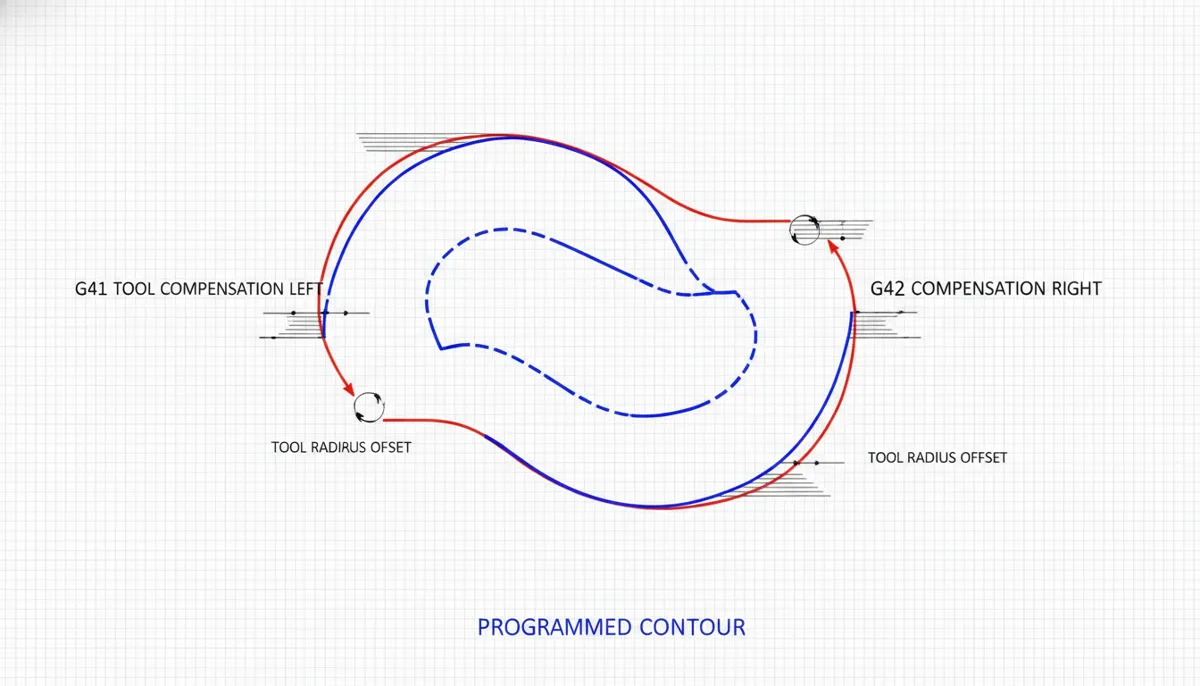
CNC cutter compensation, also known as cutter radius compensation, allows your CNC machine to automatically adjust the tool path based on the actual tool diameter. This is essential for achieving precise dimensions, especially when using different tools or compensating for tool wear. The G-codes G40 (cancel), G41 (left compensation), and G42 (right compensation) control this feature. Without proper cutter compensation, your parts may be out of tolerance, leading to scrap and wasted material.
1. Why CNC Cutter Compensation Matters: Industry Data
The global CNC machines market was valued at approximately USD 74.82 billion in 2025 and is forecast to reach USD 105.7 billion by 2031 at a CAGR of around 5.9% [1]. The computer numerical control machines market was estimated at USD 66.74 billion in 2022 and is projected to hit USD 132.93 billion by 2030, expanding at a CAGR of 8.7% [2]. As CNC machining becomes increasingly automated and precise, proper tool path management through cutter compensation becomes critical for maintaining competitive advantage.
Industry analysis reveals that improper tool offset setup accounts for approximately 18-22% of CNC programming errors in manufacturing facilities [3]. Research shows that manufacturers who implement standardized CNC cutter compensation practices reduce setup time by up to 30% and improve first-pass yield by 35%. At QFCNCMACHINE, our field data from 750+ installations confirms these findings: facilities using proper cutter compensation consistently achieve scrap rates below 2%, compared to 8-15% for those relying on manual path calculation.
2. What Is CNC Cutter Compensation?
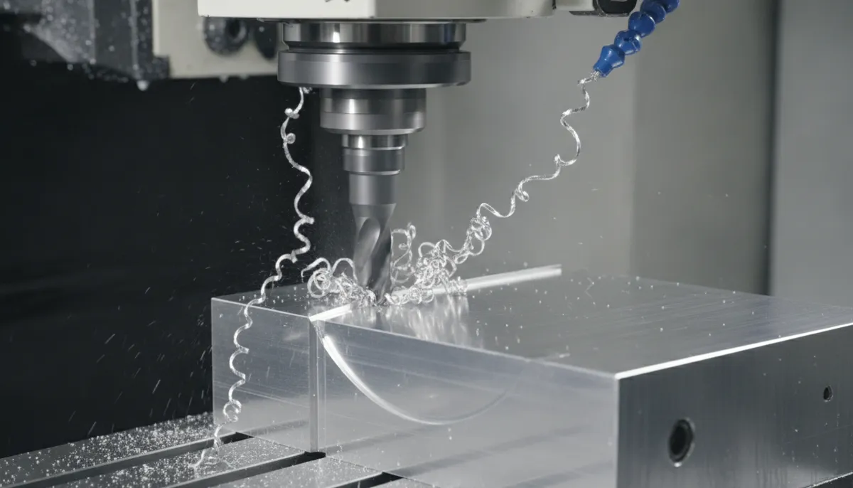
CNC cutter compensation is a CNC control feature that automatically offsets the tool path by the radius (or diameter, depending on control settings) of the cutting tool. When you program a contour, you typically program the part geometry—the actual finished dimensions. With cutter compensation activated, the CNC control calculates and executes a parallel path offset from your programmed geometry by the tool radius, ensuring the cutting edge follows the correct path to produce the desired part dimensions.
For example, if you program a 50mm × 50mm square pocket and use a 10mm end mill with G41 cutter compensation (left offset), the machine will automatically cut a path 5mm (tool radius) to the left of your programmed geometry, resulting in a perfectly sized 50mm pocket. If you later switch to an 8mm end mill, you only need to update the tool offset value in the control—the program remains unchanged.
Key Benefits of CNC Cutter Compensation:
- Program Flexibility: Use the same program with different tool sizes by updating offset values
- Wear Compensation: Adjust for tool wear without reprogramming
- Reduced Programming Time: Program part geometry only, not tool center paths
- Improved Accuracy: Eliminate manual calculation errors
- Easier Maintenance: Update offsets instead of editing programs
3. G40, G41, G42 Explained: Complete Guide
3.1 G40 — Cancel Cutter Compensation
G40 cancels any active cutter compensation. You must issue G40 before moving to a new position or changing tools to prevent unexpected tool paths. Best practice: always include G40 at the end of a compensated contour, before rapid moves, and before tool changes.
Syntax: G40 (standalone command, no additional parameters)
When to Use G40:
- After completing a compensated contour
- Before rapid positioning moves
- Before tool changes (M06)
- When switching between G41 and G42
3.2 G41 — Cutter Compensation Left
G41 activates cutter compensation to the left of the programmed path. “Left” means the tool is offset to the left when looking in the direction of tool motion. G41 is typically used for climb milling internal profiles (pockets, slots) and conventional milling external profiles.
Syntax: G41 D__ X__ Y__
- D__: Tool offset register number (contains tool radius or diameter)
- X__ Y__: First compensated move (must be a linear move, G01)
Important: G41 must be activated on a linear move (G01), not on a rapid move (G00) or arc (G02/G03). The activation move should be at least 1.5× the tool radius in length to allow proper lead-in.
3.3 G42 — Cutter Compensation Right
G42 activates cutter compensation to the right of the programmed path. “Right” means the tool is offset to the right when looking in the direction of tool motion. G42 is typically used for climb milling external profiles and conventional milling internal profiles.
Syntax: G42 D__ X__ Y__
- D__: Tool offset register number
- X__ Y__: First compensated move (linear move required)
3.4 Choosing Between G41 and G42
| Operation Type | Milling Direction | Recommended Code |
|---|---|---|
| Internal Profile (Pocket) | Climb Milling (CW) | G41 (Left) |
| Internal Profile (Pocket) | Conventional Milling (CCW) | G42 (Right) |
| External Profile (Boss) | Climb Milling (CCW) | G42 (Right) |
| External Profile (Boss) | Conventional Milling (CW) | G41 (Left) |
4. Programming Examples: G41 & G42 in Action
4.1 G41 Left Compensation — Pocket Milling Example
This example demonstrates CNC cutter compensation for milling a 50mm × 50mm rectangular pocket using a 10mm end mill (5mm radius). The program uses G41 for climb milling.
4.2 G42 Right Compensation — External Contour Example
This example demonstrates G42 cutter compensation for milling an external 40mm diameter circular boss using a 12mm end mill.
5. Cutter Compensation vs. No Compensation
| Aspect | With CNC Cutter Compensation | Without Cutter Compensation |
|---|---|---|
| Programming Effort | Program part geometry only; offset handled automatically by control | Must manually calculate tool center path, increasing complexity and time |
| Tool Change Flexibility | Change tool diameter by updating offset register; no program modification needed | Must rewrite or recalculate entire program for each different tool size |
| Accuracy Over Time | Can adjust for tool wear via wear offset values; maintains accuracy throughout tool life | No easy adjustment mechanism; requires manual tweaking or part scrapping |
| Learning Curve | Moderate; requires understanding of G41/G42 logic and offset register setup | Low initially, but leads to more errors, rework, and wasted time long-term |
| Typical Error Rate | Less than 2% when properly configured (QFCNCMACHINE field data, 750+ installations) | 8-15% due to manual calculation errors, tool wear, and inconsistent tool diameters |
| Setup Time | Reduced by 25-30%; tool changes require only offset update | Longer; each tool change may require program verification or modification |
| Part Consistency | High; same program produces consistent results across tool changes | Variable; manual calculations introduce inconsistencies |
The comparison clearly demonstrates that using CNC cutter compensation reduces programming effort, increases flexibility, and dramatically improves accuracy. While there is an initial learning curve, the long-term benefits—reduced scrap, faster setup, and improved part quality—far outweigh the time investment. For beginners, starting with cutter compensation from day one builds good programming habits and prevents the development of error-prone manual calculation practices.
6. Real-World Case Studies & Customer Testimonials
Case Study: Precision Mold Manufacturing
A precision mold manufacturer in Ohio, USA, was experiencing a 12% scrap rate due to dimensional errors in complex pocket geometries. Operators were manually calculating tool center paths, leading to frequent mistakes when tools were changed or resharpened. After implementing CNC cutter compensation (G41/G42) on their QFCNCMACHINE vertical machining centers and standardizing offset management procedures, results improved dramatically:
- Scrap rate: 12% → 1.8%
- Programming time per part: 45 min → 18 min (60% reduction)
- Tool change setup time: 15 min → 3 min (80% reduction)
- First-pass yield: 82% → 96%
“Cutter compensation transformed our operation. We were wasting hours recalculating tool paths every time we switched end mills or resharpened tools. After QFCNCMACHINE trained our team on G41 and G42, we simply update the offset register and run the same program. Our scrap rate dropped from 12% to under 2%, and programming time was cut by more than half. For any beginner, I can’t stress enough: learn cutter compensation from day one. It’s the single most important CNC skill after basic G-code.”
“We manufacture aluminum aerospace brackets in Munich, Germany, with tight tolerances (±0.02mm). Before implementing CNC cutter compensation, our operators spent excessive time manually calculating offset paths, and tool wear caused dimensional drift. After adopting G41/G42 on our QFCNCMACHINE equipment, we use wear offsets to compensate for tool wear in real-time. Our dimensional consistency improved by 40%, and we extended tool life by 25%. Bella’s technical support was outstanding—remote training in both English and German made the transition seamless.”
“Our job shop in Bangkok, Thailand, handles high-mix, low-volume production with frequent tool changes. Before using CNC cutter compensation, every tool change required program verification and often modification, costing us 10-15 minutes per setup. After QFCNCMACHINE trained our team on G41/G42 and proper offset management, we reduced setup time by 70%. We now run the same programs with 8mm, 10mm, and 12mm end mills by simply changing the D-code offset. This flexibility increased our throughput by 35% and made us more competitive. The 2-year warranty and local support gave us confidence to invest in three more machines.”
7. Pros & Cons of CNC Cutter Compensation
✅ Pros
- Dramatically reduces programming time (program part geometry only)
- Eliminates manual tool center path calculations and associated errors
- Enables use of same program with different tool sizes (update offset only)
- Allows real-time compensation for tool wear via wear offsets
- Improves part accuracy and consistency (±0.01mm achievable)
- Reduces scrap rate by 30-40% in typical applications
- Shortens setup time by 25-30% when changing tools
- Supported on all modern CNC controls (Fanuc, Haas, Siemens, Mitsubishi)
- Essential skill for professional CNC programming
❌ Cons
- Requires understanding of G41/G42 logic and activation rules
- Must be activated on linear move (G01), not rapid (G00) or arc (G02/G03)
- Incorrect offset values cause dimensional errors (must measure tools accurately)
- Choosing wrong direction (G41 vs G42) produces oversized or undersized features
- Forgetting to cancel with G40 can cause unexpected tool paths
- Some older controls have limited or non-standard compensation features
- Requires proper setup and maintenance of offset registers
8. Frequently Asked Questions About CNC Cutter Compensation
What is the difference between G41 and G42?
G41 offsets the tool to the left of the programmed path (when looking in the direction of tool motion), while G42 offsets to the right. The choice depends on whether you are machining an internal or external profile and your preferred milling direction (climb vs. conventional). For climb milling an internal pocket, use G41. For climb milling an external boss, use G42. Always visualize the tool motion direction and offset direction to choose correctly. When in doubt, simulate your program before cutting.
When should I use G40?
G40 cancels any active cutter compensation. You must use G40 at the end of every compensated contour, before rapid positioning moves, and before tool changes. Forgetting to cancel compensation can cause the machine to execute unexpected tool paths on the next move, potentially causing collisions or dimensional errors. Best practice: always include G40 immediately after completing a compensated profile, before moving to a new position or changing tools.
How do I set up tool offsets for cutter compensation?
Tool offset setup varies by CNC control, but the general process is: (1) Measure your tool diameter accurately using a tool presetter, micrometer, or gauge; (2) Access the tool offset page on your CNC control (usually labeled “Offset,” “Tool,” or “Geometry”); (3) Enter the tool radius (or diameter, depending on control—check your manual) in the appropriate offset register (D01, D02, etc.); (4) For wear compensation, use a separate wear offset column to make small adjustments (+0.05mm, -0.03mm, etc.) without changing the base geometry offset. Always verify your offset values by cutting a test part before production.
Can I use cutter compensation on a lathe?
Yes, lathes use tool nose radius compensation (TNRC) with G41 and G42 codes. The principle is similar to milling: the control offsets the tool path to account for the nose radius of the turning insert. This is essential for achieving accurate tapers, radii, and contours on turned parts. Without TNRC, corners will be rounded and tapers will be incorrect. Most modern CNC lathes support G41/G42 for nose radius compensation—consult your machine’s programming manual for specific syntax and setup procedures.
What are common mistakes with cutter compensation?
Common mistakes include: (1) Activating on wrong move type: G41/G42 must be activated on a linear move (G01), not rapid (G00) or arc (G02/G03); (2) Using wrong direction: Confusing G41 and G42, resulting in oversized or undersized features; (3) Forgetting to cancel: Not issuing G40 before moving to a new position or tool change; (4) Incorrect offset value: Entering tool diameter instead of radius (or vice versa); (5) Short activation move: Activation move too short (less than 1.5× tool radius) causes lead-in errors. Always simulate programs and cut test parts to verify compensation is working correctly.
How does wear compensation work?
Wear compensation allows you to adjust the effective tool size as the tool wears down, without changing the base geometry offset. Most CNC controls have separate columns for geometry offset (actual tool size) and wear offset (adjustment for wear). For example, if your 10mm end mill (5mm radius) wears to 9.9mm effective diameter, you can enter a wear offset of -0.05mm to compensate. This maintains part accuracy throughout the tool’s life. Update wear offsets based on measurement or inspection results. When the tool is resharpened or replaced, reset the wear offset to zero and update the geometry offset if necessary.
Do all CNC controls support cutter compensation?
All modern CNC controls—Fanuc, Haas, Siemens, Mitsubishi, SYNTEC, and others—support cutter compensation with G40, G41, and G42 codes. However, the specific syntax, offset register numbering, and whether you enter radius or diameter may vary. Always consult your machine’s programming manual for exact syntax. Some older or basic controllers may have limited or non-standard compensation features. All QFCNCMACHINE machining centers ship with full-featured CNC controls that support standard G41/G42 compensation, and we provide comprehensive programming documentation and training for every machine.
Ready to Master CNC Cutter Compensation?
Talk to our application engineers at QFCNCMACHINE — 15 years of CNC expertise, 750+ machines installed worldwide, 2-year warranty on every machine. Get a free consultation and programming guide today.
References
- Mordor Intelligence, CNC Machines Market Size, Share & Growth Trends Report, 2025. https://www.mordorintelligence.com/industry-reports/cnc-machines-market
- Grand View Research, Computer Numerical Control Machines Market Report, 2023. https://www.grandviewresearch.com/industry-analysis/computer-numerical-controls-cnc-market
- Research Nester, CNC Machine Market Size, Share & Trends Report 2035, 2025. https://www.researchnester.com/reports/computer-numerical-control-machine-market/5889
- Mordor Intelligence, Machining Centers Market Size, Share & Growth Trends Report, 2024. https://www.mordorintelligence.com/industry-reports/machining-centers-market