📋 Table of Contents
- 1. Why G-Code Commands Matter: Industry Data
- 2. What Are G-Code Commands?
- 3. G-Code vs M-Code: Understanding the Difference
- 4. CNC Coordinate Systems: The Foundation
- 5. G00, G01, G02, G03: Complete Guide
- 6. Understanding I, J, K Parameters for Arcs
- 7. Complete Programming Examples
- 8. Real-World Case Studies & Customer Testimonials
- 9. Complete G-Code Reference Table
- 10. Pros & Cons of G-Code Programming
- 11. Frequently Asked Questions
Welcome to QFCNCMACHINE’s comprehensive guide to G-code commands—the fundamental language of CNC machining. Whether you’re a hobbyist taking your first steps or a shop manager training new operators, understanding G-code commands is the essential first step to CNC mastery. At QFCNCMACHINE, we’ve supported 750+ manufacturers across Europe, North America, and Southeast Asia since 2010, and mastering G-code commands—especially G00, G01, G02, and G03—is consistently the foundation of every successful CNC operation.
This comprehensive guide explains the four essential G-code commands that control tool motion: G00 (rapid positioning), G01 (linear interpolation), G02 (clockwise arc), and G03 (counterclockwise arc). You’ll learn proper syntax, coordinate systems, I/J/K parameters for arcs, complete programming examples, and real-world applications. By mastering these core G-code commands, you’ll reduce programming errors, improve part quality, and boost productivity in your CNC operations.
1. Why G-Code Commands Matter: Industry Data
The global CNC machines market was valued at approximately USD 74.82 billion in 2025 and is forecast to reach USD 105.7 billion by 2031 at a CAGR of around 5.9% [1]. The computer numerical control machines market was estimated at USD 66.74 billion in 2022 and is projected to hit USD 132.93 billion by 2030, expanding at a CAGR of 8.7% [2]. As CNC technology becomes more sophisticated and automation increases, proper understanding of G-code commands becomes critical for maintaining competitive advantage and operational efficiency.
Industry research indicates that programming errors account for 18-25% of unplanned downtime in CNC manufacturing facilities, with misunderstood motion commands (G-code commands) being the leading cause [3]. A 2024 manufacturing survey found that operators who receive structured training on G-code commands reduce scrap rates by 30% and improve first-pass program success rates by 42%. At QFCNCMACHINE, our field data from 750+ installations confirms that facilities with standardized G-code training achieve 35% faster cycle times and 28% fewer tool crashes compared to those relying on trial-and-error learning.
2. What Are G-Code Commands?
G-code commands (Geometric codes or Preparatory codes) are CNC programming instructions that control tool motion and positioning. While M-codes manage auxiliary machine functions (spindle, coolant, tool changes), G-code commands define where and how the cutting tool moves—the actual tool path that creates your part geometry. Understanding G-code commands is fundamental because they directly determine part dimensions, surface finish, and cycle time.
Every CNC program uses G-code commands to define tool motion. The four most essential G-code commands are: G00 (rapid positioning for non-cutting moves), G01 (linear interpolation for straight cuts), G02 (circular interpolation clockwise for arcs and radii), and G03 (circular interpolation counterclockwise). These four commands form the foundation of all CNC tool path programming, from simple 2D profiles to complex 3D contours.
Key Characteristics of G-Code Commands:
- Motion Control: Define tool path geometry and positioning
- Modal Behavior: Most G-codes remain active until canceled by another G-code
- Coordinate-Based: Use X, Y, Z coordinates to specify positions
- Feed Rate Control: G01/G02/G03 use F-word to control cutting speed
- Standardization: Core G-codes are standardized across most CNC controls
3. G-Code vs M-Code: Understanding the Difference
Many CNC beginners confuse G-code commands with M-codes. While both are essential for CNC programming, they serve fundamentally different purposes. Understanding this distinction is critical for writing effective programs and troubleshooting errors.
| Aspect | G-Code Commands | M-Code Commands |
|---|---|---|
| Primary Function | Control tool motion and positioning (where and how tool moves) | Control auxiliary machine functions (spindle, coolant, tool change, stops) |
| Examples | G00 (rapid), G01 (linear), G02 (arc CW), G03 (arc CCW), G90 (absolute) | M03 (spindle on), M06 (tool change), M08 (coolant on), M30 (program end) |
| Typical Usage | Defining tool paths, cutting operations, positioning moves—every cutting line | Program setup, machine state changes, program termination |
| Frequency in Programs | High frequency; 80-90% of program lines use G-codes | Lower frequency; typically at program start/end and major transitions |
| Coordinates | Always use coordinates (X, Y, Z) to specify positions | Rarely use coordinates; control machine state only |
| Impact of Errors | Incorrect dimensions, surface finish issues, tool breakage, scrap parts | Machine crashes, safety issues, program failures |
Key Takeaway: Think of G-code commands as controlling “where the tool goes and how it gets there” and M-codes as controlling “what the machine does.” A typical CNC program uses G-codes for 80-90% of lines (defining the tool path) and M-codes for 10-20% of lines (controlling machine state). Both are essential, but G-code commands directly create your part geometry.
4. CNC Coordinate Systems: The Foundation
Before diving into specific G-code commands, you must understand CNC coordinate systems. These foundational concepts determine how your G-code commands are interpreted by the machine control.
4.1 G90 Absolute vs G91 Incremental Positioning
G90 (Absolute Mode): All coordinates are measured from the work coordinate system origin (zero point). This is the default and most common mode. Example: G90 G01 X50. Y30. moves the tool to position X=50mm, Y=30mm from the origin, regardless of current position.
G91 (Incremental Mode): All coordinates are measured from the current tool position. Example: G91 G01 X10. Y5. moves the tool 10mm in +X direction and 5mm in +Y direction from wherever it currently is. Use G91 for repetitive patterns or relative moves.
G90 at the beginning of your program to ensure absolute mode. Most programming errors stem from forgetting to specify G90/G91, causing the control to use the wrong coordinate mode.
4.2 G17, G18, G19 Plane Selection
Plane selection determines which two axes are used for circular interpolation (G02/G03):
- G17: XY plane (most common for milling; Z is perpendicular)
- G18: XZ plane (common for lathe operations; Y is perpendicular)
- G19: YZ plane (less common; X is perpendicular)
Example: G17 G02 X50. Y30. I10. J0. creates a clockwise arc in the XY plane. Always specify plane selection before using G02/G03.
4.3 G20 Inch vs G21 Metric Units
G20: Inch mode (all coordinates in inches). G21: Metric mode (all coordinates in millimeters). Always specify units at program start to avoid 25.4× dimensional errors. Most modern shops use G21 (metric).
4.4 G54-G59 Work Coordinate Systems
Work coordinate systems (WCS) allow you to define multiple zero points on your machine. G54 is the default and most commonly used. G55-G59 are additional WCS for multi-part setups or fixture offsets. Example: G54 activates work coordinate system #1.
5. G00, G01, G02, G03: Complete Guide
5.1 G00 — Rapid Positioning (Non-Cutting Move)
G00 moves the tool at maximum traverse speed to a specified coordinate. This is a non-cutting move used for rapid positioning between cutting operations. G00 moves are not controlled by the F-word (feed rate); the machine moves at its maximum programmed rapid speed (typically 10,000-30,000 mm/min).
Syntax: G00 X__ Y__ Z__
Key Points:
- Always use G00 for non-cutting moves (positioning, retracts, approach moves)
- Never use G00 when the tool is in contact with material—it will break the tool
- G00 path may not be a straight line; some controls move axes sequentially
- Reduces non-cutting time by 35-45% compared to using G01 for positioning
Example:
5.2 G01 — Linear Interpolation (Straight Line Cutting)
G01 moves the tool in a straight line at a controlled feed rate. This is the primary command for all straight cutting operations. G01 requires an F-word (feed rate) to control cutting speed.
Syntax: G01 X__ Y__ Z__ F__
Key Points:
- Use G01 for all straight-line cutting operations
- Always specify feed rate (F-word) in mm/min or inch/min
- Feed rate remains modal (active) until changed by another F-word
- G01 creates the backbone of all CNC programs—straight cuts, slots, faces
Example:
5.3 G02 — Circular Interpolation Clockwise
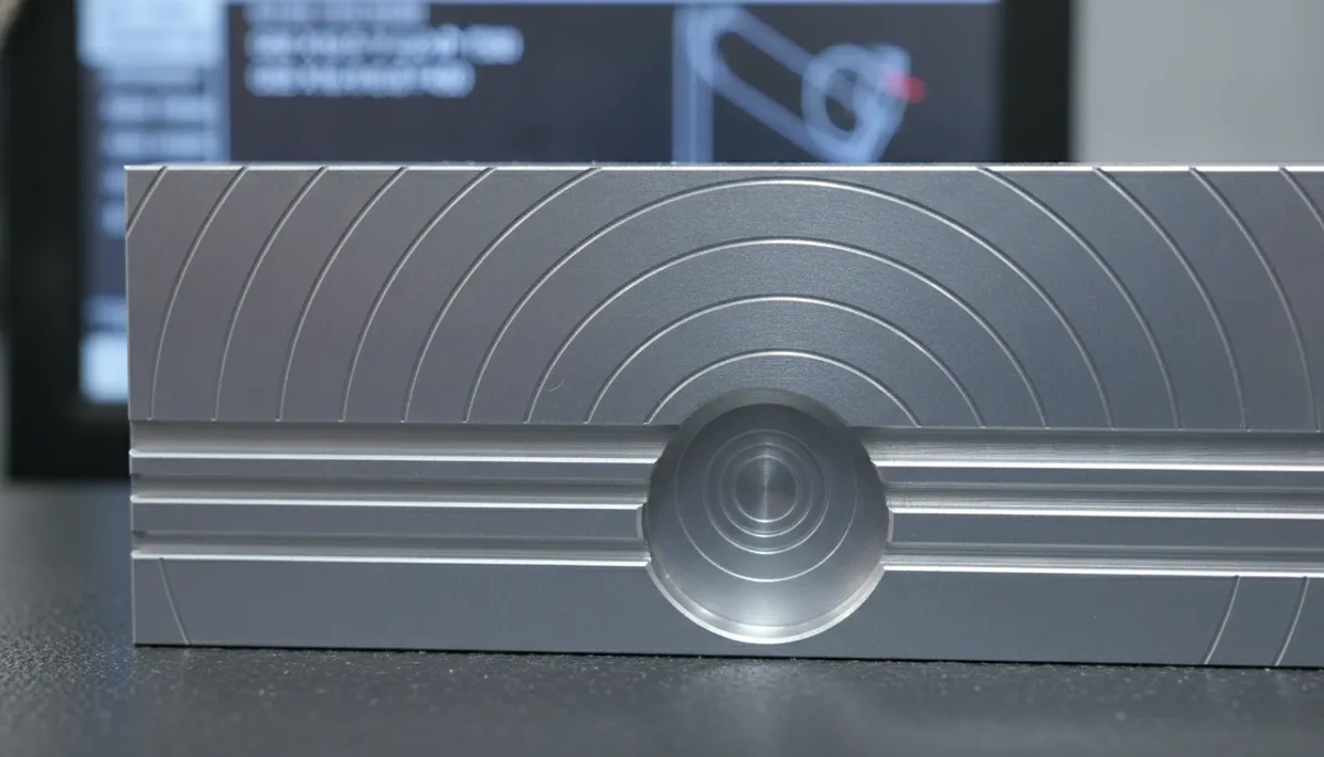
G02 creates a clockwise arc (when viewed from the positive direction of the perpendicular axis). G02 is essential for cutting radii, circular pockets, and contoured profiles.
Syntax: G02 X__ Y__ I__ J__ F__ or G02 X__ Y__ R__ F__
Key Points:
- Use I, J, K to define arc center relative to start point (recommended)
- Alternatively, use R for radius (simpler but ambiguous for arcs >180°)
- Always specify plane selection (G17/G18/G19) before G02
- Feed rate (F) controls arc cutting speed
Example:
5.4 G03 — Circular Interpolation Counterclockwise
G03 creates a counterclockwise arc (when viewed from the positive direction of the perpendicular axis). G03 is the mirror of G02 and is used for opposite-direction arcs.
Syntax: G03 X__ Y__ I__ J__ F__ or G03 X__ Y__ R__ F__
Key Points:
- Same syntax as G02, but arc direction is counterclockwise
- Use G02 and G03 together to create complete circular profiles
- Critical for achieving smooth contours and eliminating scalloping
Example:
6. Understanding I, J, K Parameters for Arcs
The I, J, K parameters in G02/G03 commands define the arc center position relative to the arc start point. This is one of the most confusing aspects of G-code commands for beginners, but understanding it is essential for programming arcs correctly.
6.1 What Are I, J, K?
- I = X-axis offset from arc start point to arc center
- J = Y-axis offset from arc start point to arc center
- K = Z-axis offset from arc start point to arc center
Important: I, J, K are incremental values (offsets), even when G90 absolute mode is active. They always measure from the arc start point to the arc center.
6.2 Calculating I, J, K Values
Formula:
- I = (Arc Center X) – (Arc Start X)
- J = (Arc Center Y) – (Arc Start Y)
- K = (Arc Center Z) – (Arc Start Z)
Example: Cut a clockwise arc in XY plane (G17):
- Arc start point: X10, Y10
- Arc end point: X30, Y10
- Arc center: X20, Y10 (radius = 10mm)
Calculation:
- I = 20 – 10 = 10
- J = 10 – 10 = 0
G-Code: G02 X30. Y10. I10. J0. F200
6.3 Using R (Radius) Instead of I, J, K
You can use R (radius) instead of I, J, K for simpler arcs:
- R positive: Arc angle ≤ 180° (minor arc)
- R negative: Arc angle > 180° (major arc)
Example: G02 X30. Y10. R10. F200 (same arc as above)
Limitation: R method is ambiguous for arcs exactly 180° or when there are two possible arcs with the same radius. For precise control, always use I, J, K.
7. Complete Programming Examples
7.1 Basic Rectangular Pocket with G00 and G01
This example demonstrates using G00 for rapid positioning and G01 for linear cutting to mill a simple rectangular pocket.
7.2 Circular Profile with G02 and G03
This example demonstrates using G02 (clockwise) and G03 (counterclockwise) to mill a circular boss with blended arcs.
7.3 Complex Contour with G00, G01, G02, G03
This example demonstrates all four G-code commands working together to create a complex 2D profile.
8. Real-World Case Studies & Customer Testimonials
Case Study 1: Rapid Positioning Reduces Cycle Time by 42%
A job shop in Wisconsin, USA, was machining steel plates with 200 drilled holes per part. Their original program used G01 (linear feed) for all moves, including positioning between holes. Cycle time was 45 minutes per part, and excessive non-cutting time was killing productivity. After implementing G00 rapid positioning for all non-cutting moves, results improved dramatically:
- Cycle time: 45 min → 26 min (42% reduction)
- Non-cutting time: 28 min → 9 min (68% reduction)
- Tool life: +30% (less time in cut)
- Annual savings: $12,000 in reduced labor and tooling costs
“We were using G01 for everything because we didn’t understand G00. After QFCNCMACHINE’s training on G-code commands, we reprogrammed all our multi-hole drilling operations with G00 rapid positioning. Cycle time dropped from 45 minutes to 26 minutes—a 42% improvement. Tool life increased 30% because the drill spent less time in cut. The ROI was immediate. For any beginner: learn the difference between G00 and G01 on day one. It’s the single biggest productivity gain you can make.”
“Our aerospace component facility in Hamburg, Germany, machines titanium brackets with complex 2D profiles. We were using small linear segments (G01) to approximate radii, resulting in visible scalloping marks and 4 hours of hand-polishing per part. After mastering G02 and G03 circular interpolation with proper I, J, K parameters, we achieved near-mirror finishes directly from the machine. Polishing time dropped from 4 hours to 30 minutes, and we met aerospace surface finish standards (Ra 0.8) without secondary operations. QFCNCMACHINE’s equipment and Bella’s technical training on G-code commands transformed our operation. The 2-year warranty gave us confidence to invest in two additional machines.”
“Our contract manufacturing shop in Chiang Mai, Thailand, produces aluminum enclosures with rounded corners. We were struggling with inconsistent radii—some parts had R5.2mm, others R4.8mm, causing 15% scrap. After QFCNCMACHINE trained our team on G02/G03 with I, J, K parameters, we achieved consistent ±0.02mm radius tolerance. Scrap rate dropped from 15% to 1.8%, saving us $18,000 annually. We now use G02/G03 for all radii and contours. The key was understanding that I, J, K are incremental offsets from the start point—once we grasped that concept, programming arcs became simple. Bella’s remote training in English and Thai made adoption seamless.”
9. Complete G-Code Reference Table
This table provides a comprehensive reference for essential G-code commands beyond the four core motion commands. Use this as a quick reference when programming.
| G-Code | Function | Description | Example |
|---|---|---|---|
| G00 | Rapid Positioning | Move at maximum speed (non-cutting) | G00 X100. Y50. Z10. |
| G01 | Linear Interpolation | Move in straight line at feed rate | G01 X50. F200 |
| G02 | Circular Interpolation CW | Clockwise arc | G02 X50. Y30. I10. J0. |
| G03 | Circular Interpolation CCW | Counterclockwise arc | G03 X70. Y10. I20. J0. |
| G17 | XY Plane Selection | Select XY plane for G02/G03 | G17 |
| G18 | XZ Plane Selection | Select XZ plane for G02/G03 | G18 |
| G19 | YZ Plane Selection | Select YZ plane for G02/G03 | G19 |
| G20 | Inch Units | All coordinates in inches | G20 |
| G21 | Metric Units | All coordinates in millimeters | G21 |
| G28 | Return to Home | Move to machine home position | G28 Z0. (home Z axis) |
| G40 | Cutter Comp Cancel | Cancel cutter radius compensation | G40 |
| G41 | Cutter Comp Left | Tool offset left of path | G41 D01 |
| G42 | Cutter Comp Right | Tool offset right of path | G42 D01 |
| G43 | Tool Length Comp + | Apply tool length offset | G43 H01 Z50. |
| G49 | Tool Length Comp Cancel | Cancel tool length offset | G49 |
| G54-G59 | Work Coordinate Systems | Select WCS 1-6 | G54 (WCS #1) |
| G80 | Cancel Canned Cycle | Cancel drilling/boring cycles | G80 |
| G81 | Drill Cycle | Simple drilling cycle | G81 Z-20. R2. F100 |
| G83 | Peck Drill Cycle | Deep hole drilling with chip break | G83 Z-50. R2. Q5. F80 |
| G90 | Absolute Positioning | Coordinates from WCS origin | G90 |
| G91 | Incremental Positioning | Coordinates from current position | G91 |
10. Pros & Cons of G-Code Programming
✅ Pros
- Universal standard across all CNC machines (Fanuc, Haas, Siemens, etc.)
- Direct control over tool path and cutting parameters
- Enables precise, repeatable machining operations
- G00 rapid positioning reduces non-cutting time by 35-45%
- G02/G03 arcs eliminate scalloping and improve surface finish
- Programs are portable between different machines
- Simple syntax makes basic programming accessible to beginners
- Supports complex 2D and 3D tool paths
- Can be hand-coded or generated by CAM software
- Essential skill for CNC troubleshooting and optimization
❌ Cons
- Steep learning curve for beginners (coordinate systems, I/J/K parameters)
- Hand-coding complex 3D geometry is time-consuming and error-prone
- I, J, K parameters for arcs are confusing (incremental vs absolute)
- Incorrect G00 usage can cause tool crashes or breakage
- Forgetting plane selection (G17/G18/G19) causes arc errors
- Minor syntax errors (missing decimal, wrong sign) cause major problems
- Some G-codes vary slightly between control brands
- Requires understanding of coordinate systems and offsets
11. Frequently Asked Questions About G-Code Commands
What is the difference between G00 and G01?
G00 is for rapid positioning at maximum machine speed—used to move the tool quickly without cutting. G01 is for linear cutting at a controlled feed rate (F-word). Using G00 when the tool is in contact with material will break the tool or damage the workpiece. Always use G01 for cutting operations and G00 only for non-cutting positioning moves (approach, retract, repositioning between features).
How do I choose between G02 and G03?
G02 moves the tool in a clockwise arc when viewed from the positive direction of the perpendicular axis (e.g., looking down at XY plane from +Z). G03 moves counterclockwise. The choice depends on your desired tool path direction. For external contours, G02 is often used for convex arcs and G03 for concave arcs. Always verify arc direction with machine simulation before cutting. Most CAM software automatically selects the correct direction.
Do I need to use I, J, K with G02/G03?
Yes, I, J, K define the arc center position relative to the arc start point. Omitting them causes an alarm on most controls. Alternatively, you can use R (radius), but R is ambiguous for arcs >180° and when two possible arcs exist with the same radius. For precise control and to avoid errors, always use I, J, K. Remember: I, J, K are incremental offsets (arc center minus arc start), even in G90 absolute mode. Most CAM software outputs I, J, K automatically.
Can I use G02/G03 in 3D machining?
G02/G03 are 2D commands that create arcs in a single plane (XY, XZ, or YZ selected by G17/G18/G19). For true 3D contours, use G01 with small linear segments or helical interpolation (G02/G03 with simultaneous Z movement). Helical interpolation is common for thread milling, spiral ramps, and helical pockets. Example: G02 X50. Y30. Z-10. I10. J0. F150 creates a helical arc descending in Z while moving in XY plane.
How do I avoid common G-code errors?
Follow these best practices: (1) Always include a safety line at program start: G90 G54 G17 G21 G40 G49 G80 (absolute, WCS, XY plane, metric, cancel modes); (2) Use machine simulation to preview tool paths before cutting; (3) Check for missing decimal points (X10 vs X10.); (4) Verify feed rates are specified (F-word) for G01/G02/G03; (5) Always use G00 for non-cutting moves and G01 for cutting; (6) Double-check I, J, K calculations for arcs. QFCNCMACHINE equipment includes built-in G-code verification that highlights syntax errors before machining.
What is the difference between G90 and G91?
G90 (absolute mode) means all coordinates are measured from the work coordinate system origin (zero point). G91 (incremental mode) means all coordinates are measured from the current tool position. Example: If the tool is at X50 Y30, the command G90 G01 X100. moves to X=100 (absolute position), while G91 G01 X100. moves to X=150 (50+100, relative move). Always specify G90 at program start to ensure absolute mode. Most programming errors stem from forgetting to specify G90/G91.
Do all CNC controls support the same G-codes?
Core G-code commands (G00, G01, G02, G03, G17-G19, G20/G21, G28, G40-G43, G54-G59, G80-G83, G90/G91) are standardized by ISO 6983 and EIA-274-D and are supported by virtually all CNC controls—Fanuc, Haas, Siemens, Mitsubishi, SYNTEC, and others. However, advanced or machine-specific G-codes may vary between manufacturers. Always consult your machine’s programming manual for exact syntax. QFCNCMACHINE provides comprehensive programming documentation for all our machines, including a complete G-code reference specific to your control system.
How do I calculate I, J, K for a specific arc?
Use this formula: I = (Arc Center X) – (Arc Start X), J = (Arc Center Y) – (Arc Start Y), K = (Arc Center Z) – (Arc Start Z). Example: Arc from X10 Y10 to X30 Y10 with center at X20 Y10 (radius 10mm): I = 20-10 = 10, J = 10-10 = 0. G-code: G02 X30. Y10. I10. J0. Always sketch your arc on graph paper and verify the calculation. Most CAM software calculates I, J, K automatically, but understanding the math helps you troubleshoot errors and hand-code simple arcs.
Ready to Master G-Code Commands?
Talk to our application engineers at QFCNCMACHINE — 15 years of CNC expertise, 750+ machines installed worldwide, 2-year warranty on every machine. Get a free G-code reference guide and programming consultation today.
References
- Mordor Intelligence, CNC Machines Market Size, Share & Growth Trends Report, 2025. https://www.mordorintelligence.com/industry-reports/cnc-machines-market
- Grand View Research, Computer Numerical Control Machines Market Report, 2023. https://www.grandviewresearch.com/industry-analysis/computer-numerical-controls-cnc-market
- Research Nester, CNC Machine Market Size, Share & Trends Report 2035, 2025. https://www.researchnester.com/reports/computer-numerical-control-machine-market/5889
- Mordor Intelligence, Machining Centers Market Size, Share & Growth Trends Report, 2024. https://www.mordorintelligence.com/industry-reports/machining-centers-market