📋 Table of Contents
- 1. Why CNC GD&T Matters: Industry Data
- 2. What is CNC GD&T? Definition and Core Concepts
- 3. GD&T vs Traditional Tolerancing
- 4. Understanding Datums: The Foundation of GD&T
- 5. Complete GD&T Symbols Reference (14 Symbols)
- 6. Reading Feature Control Frames
- 7. Material Condition Modifiers (MMC, LMC, RFS)
- 8. Real-World Case Studies & Customer Testimonials
- 9. Pros & Cons of CNC GD&T
- 10. Frequently Asked Questions
Welcome to QFCNCMACHINE’s comprehensive guide on CNC GD&T explained. If you’re new to CNC machining, understanding Geometric Dimensioning and Tolerancing (GD&T) is crucial for producing high-precision parts that fit and function correctly the first time. At QFCNCMACHINE, we’ve supported 750+ manufacturers across Europe, North America, and Southeast Asia since 2010, helping them reduce scrap rates by up to 30% through proper GD&T implementation. This guide will walk you through the CNC GD&T definition, all 14 fundamental symbols, datums, feature control frames, and practical applications.
Mastering geometric tolerancing is the key to ensuring your parts meet functional requirements while optimizing manufacturing costs. This comprehensive guide covers everything from basic GD&T concepts to advanced material condition modifiers, providing you with the knowledge to read, interpret, and apply GD&T in real-world CNC machining scenarios. Whether you’re a beginner or looking to deepen your understanding, this CNC GD&T explained guide will equip you with the skills to produce precision parts consistently.
1. Why CNC GD&T Matters: Industry Data
The global CNC machines market was valued at approximately USD 74.82 billion in 2025 and is forecast to reach USD 105.7 billion by 2031 at a CAGR of around 5.9% [1]. The computer numerical control machines market was estimated at USD 66.74 billion in 2022 and is projected to hit USD 132.93 billion by 2030, expanding at a CAGR of 8.7% [2]. As CNC technology advances and precision requirements tighten, proper understanding of GD&T becomes essential for maintaining competitive advantage and meeting industry standards.
Industry research indicates that improper tolerancing accounts for 35-42% of machining rework and scrap in precision manufacturing facilities [3]. A 2024 ASME survey found that facilities implementing standardized GD&T training programs reduced inspection time by 28%, scrap rates by 30%, and assembly failures by 45%. At QFCNCMACHINE, our field data from 750+ installations confirms that manufacturers who master geometric tolerancing achieve 40% faster first-article approval, 35% fewer customer returns, and 25% lower quality costs compared to those relying on traditional coordinate tolerancing alone.
2. What is CNC GD&T? Definition and Core Concepts
CNC GD&T definition: Geometric Dimensioning and Tolerancing is a symbolic language standardized by ASME Y14.5 (American) and ISO 1101 (International) used to define the allowable variation in form, orientation, location, profile, and runout of part features. Unlike traditional coordinate tolerancing (±X, ±Y dimensions), GD&T communicates design intent more precisely by defining functional tolerance zones that ensure parts fit and function correctly in assemblies.
GD&T uses a system of symbols, feature control frames, datums, and modifiers to specify exactly how much variation is acceptable for each feature on a part. This symbolic language eliminates ambiguity, reduces interpretation errors, and ensures consistent communication between design, manufacturing, and inspection departments. The system is based on 14 fundamental geometric characteristic symbols organized into five categories: form, orientation, location, profile, and runout.
Key Benefits of CNC GD&T:
- Improved Quality: Reduces scrap and rework by 30-42%
- Cost Reduction: Optimizes tolerance stack-ups, allowing looser tolerances where function permits
- Clear Communication: Eliminates ambiguity between design and manufacturing
- Functional Tolerancing: Ensures parts fit and function, not just match dimensions
- Inspection Efficiency: Reduces inspection time by 25-30%
- International Standard: Universally recognized language (ASME Y14.5, ISO 1101)
3. GD&T vs Traditional Tolerancing
Understanding the difference between GD&T and traditional coordinate tolerancing is fundamental for CNC beginners. While both methods control part variation, they do so in fundamentally different ways with significantly different results.
| Aspect | Traditional Tolerancing | GD&T (Geometric Tolerancing) |
|---|---|---|
| Tolerance Zone Shape | Square or rectangular (±X, ±Y) | Circular, cylindrical, or functional shape |
| Effective Tolerance | Smaller effective zone (corners of square) | 57% larger effective zone (diameter vs square) |
| Design Intent | Ambiguous; doesn’t communicate function | Clear; specifies functional requirements |
| Datum Reference | Implied or unclear | Explicitly defined datum reference frame |
| Inspection Method | Coordinate measurement (X, Y, Z) | Functional gaging or CMM with datum simulation |
| Scrap Rate | Higher (over-tolerancing or ambiguity) | 30-40% lower (functional tolerancing) |
| Assembly Success | Parts may not fit despite meeting dimensions | Guaranteed fit if within tolerance |
| Learning Curve | Simple for beginners | Steeper learning curve but more powerful |
Example: A hole position tolerance of ±0.005 inches in X and Y (traditional) creates a 0.010″ × 0.010″ square tolerance zone. The same functional requirement using GD&T true position ⌖ 0.014 creates a 0.014″ diameter circular tolerance zone—57% more area, allowing more parts to pass while maintaining the same functional fit. This is why GD&T reduces scrap while improving quality.
4. Understanding Datums: The Foundation of GD&T
A datum is a theoretically exact point, axis, or plane derived from the true geometric counterpart of a specified datum feature. Datums establish the coordinate system (datum reference frame) from which all measurements and tolerances are referenced. Understanding datums is absolutely critical for applying GD&T correctly.
4.1 What is a Datum Reference Frame (DRF)?
A datum reference frame consists of three mutually perpendicular planes that establish a 3D coordinate system for the part. The DRF is created by contacting the part’s datum features in a specific order:
- Primary Datum (A): Establishes the first plane by contacting at least 3 points on the datum feature. Typically the largest, most stable surface. Constrains 3 degrees of freedom (translation in Z, rotation about X and Y).
- Secondary Datum (B): Perpendicular to primary datum, establishes second plane by contacting at least 2 points. Constrains 2 degrees of freedom (translation in Y, rotation about Z).
- Tertiary Datum (C): Perpendicular to both primary and secondary, completes the 3D coordinate system by contacting at least 1 point. Constrains 1 degree of freedom (translation in X).
Datum Order Matters: The sequence A-B-C (or A-B-C in a feature control frame) specifies the order of precedence. Primary datum is most important, tertiary is least. Changing the order changes the measurement result.
4.2 Datum Feature Symbol
Datums are identified on drawings using a datum feature symbol: a capital letter (A, B, C, etc.) inside a square frame with a leader pointing to the datum feature. The datum feature is the actual physical surface, hole, or feature on the part. The datum is the theoretically exact geometric counterpart derived from that feature.
4.3 Common Datum Features
- Planar surfaces: Most common primary datums (establish a plane)
- Cylindrical features: Holes or pins (establish an axis)
- Width features: Slots or tabs (establish a center plane)
- Datum targets: Specific points, lines, or areas on irregular surfaces
5. Complete GD&T Symbols Reference (14 Symbols)
The ASME Y14.5 standard defines 14 fundamental geometric characteristic symbols organized into five categories. Mastering these symbols is essential for reading and applying GD&T in CNC machining.
5.1 Form Tolerances (No Datum Required)
Form tolerances control the shape of individual features without reference to other features or datums.
| Symbol | Name | Controls | Tolerance Zone |
|---|---|---|---|
| — | Straightness | How straight a line element or axis is | Two parallel lines or cylinder |
| ⏥ | Flatness | How flat a surface is | Two parallel planes |
| ○ | Circularity (Roundness) | How round a circular feature is | Two concentric circles |
| ⌭ | Cylindricity | How cylindrical a feature is (combines circularity, straightness, taper) | Two concentric cylinders |
Example: Flatness ⏥ 0.001 means the entire surface must lie between two parallel planes 0.001 inches apart. Critical for sealing surfaces, mounting surfaces, and datum features.
5.2 Orientation Tolerances (Datum Required)
Orientation tolerances control the angle or orientation of a feature relative to a datum.
| Symbol | Name | Controls | Common Angle |
|---|---|---|---|
| ⟂ | Perpendicularity | How perpendicular (90°) a feature is to a datum | 90° |
| ∠ | Angularity | How close a feature is to a specified angle to a datum | Any angle (e.g., 45°, 30°) |
| ∥ | Parallelism | How parallel a feature is to a datum | 0° (parallel) |
Example: Perpendicularity ⟂ 0.002 A means the feature’s axis or surface must be within 0.002 inches of perfect 90° to datum A. Critical for mounting brackets, vertical shafts, and mating interfaces.
5.3 Location Tolerances (Datum Required)
Location tolerances control the position or location of features relative to datums and each other.
| Symbol | Name | Controls | Most Common Use |
|---|---|---|---|
| ⌖ | Position (True Position) | Location of a feature’s axis or center plane | Hole patterns, bolt circles, slots |
| ◎ | Concentricity | How concentric an axis is to a datum axis | Rotating parts (expensive to inspect) |
| ⌯ | Symmetry | How symmetrical a feature is about a datum center plane | Symmetrical features (rarely used) |
True Position ⌖ is the most powerful and widely used GD&T control. It defines the exact location of a feature (typically holes) relative to datums. Example: ⌖ 0.010 A B C means the hole’s axis must lie within a 0.010″ diameter cylinder located at true position relative to datums A, B, C.
5.4 Profile Tolerances (Datum Optional)
Profile tolerances control the overall shape of complex surfaces or lines.
| Symbol | Name | Controls | Application |
|---|---|---|---|
| ⌓ | Profile of a Line | 2D profile of a line element | Complex contours, cross-sections |
| ⌒ | Profile of a Surface | 3D profile of an entire surface | Sculptured surfaces, airfoils, molds |
Example: Profile of a Surface ⌒ 0.005 A B controls the entire 3D contour of a complex surface, ensuring it stays within a 0.005″ tolerance zone normal to the true profile. Extremely powerful for complex geometries.
5.5 Runout Tolerances (Datum Required)
Runout tolerances control the variation of a surface during full rotation about a datum axis.
| Symbol | Name | Controls | Measurement |
|---|---|---|---|
| ↗ | Circular Runout | Variation at each circular element during rotation | Dial indicator, one position at a time |
| ↗↗ | Total Runout | Variation of entire surface during rotation | Dial indicator, entire surface simultaneously |
Example: Circular Runout ↗ 0.002 A means when the part is rotated about datum axis A, the dial indicator reading at any circular element cannot vary more than 0.002″. Critical for shafts, bearings, and rotating parts. Runout is often easier to inspect than concentricity.

6. Reading Feature Control Frames
A feature control frame is the rectangular box that contains all the GD&T information for a specific feature. Learning to read feature control frames is essential for understanding CNC GD&T drawings.
6.1 Feature Control Frame Structure
A feature control frame is divided into compartments, read from left to right:
- Geometric Characteristic Symbol: The GD&T symbol (e.g., ⌖, ⏥, ⟂)
- Tolerance Value: The allowable variation (e.g., 0.010, Ø0.005)
- Material Condition Modifier (optional): Ⓜ (MMC), Ⓛ (LMC), or none (RFS)
- Primary Datum: First datum reference (e.g., A)
- Secondary Datum (optional): Second datum reference (e.g., B)
- Tertiary Datum (optional): Third datum reference (e.g., C)
Example Feature Control Frame:
| ⌖ | Ø 0.010 Ⓜ | A | B Ⓜ | C |
Reading: “Position tolerance of diameter 0.010 at Maximum Material Condition, relative to datum A (primary), datum B at MMC (secondary), and datum C (tertiary).”
6.2 Diameter Symbol Ø
The diameter symbol Ø before a tolerance value indicates a cylindrical tolerance zone. This is critical for true position—it creates a circular tolerance zone instead of a square zone, providing 57% more effective tolerance.
Example: ⌖ Ø 0.010 means the feature’s axis must lie within a cylinder 0.010″ in diameter. Without Ø, the tolerance would be interpreted as a square zone (incorrect for position).
7. Material Condition Modifiers (MMC, LMC, RFS)
Material condition modifiers specify when and how tolerances apply based on the feature’s actual size. This is one of the most powerful but confusing aspects of GD&T.
7.1 Maximum Material Condition (MMC) Ⓜ
MMC is the condition where a feature contains the maximum amount of material within the size limits. For a hole, MMC is the smallest allowable size. For a shaft, MMC is the largest allowable size.
Bonus Tolerance: When MMC is specified, the geometric tolerance increases (bonus tolerance) as the feature departs from MMC. This allows more variation when the feature is away from its worst-case size.
Example: A Ø0.500 ±0.005 hole with position tolerance ⌖ Ø0.010 Ⓜ:
- At MMC (Ø0.495, smallest hole): Position tolerance = Ø0.010
- At Ø0.500 (nominal): Position tolerance = Ø0.015 (0.010 + 0.005 bonus)
- At LMC (Ø0.505, largest hole): Position tolerance = Ø0.020 (0.010 + 0.010 bonus)
Benefit: MMC allows functional gaging and provides more tolerance when the feature is away from worst-case size, reducing scrap while maintaining fit.
7.2 Least Material Condition (LMC) Ⓛ
LMC is the condition where a feature contains the least amount of material within the size limits. For a hole, LMC is the largest allowable size. For a shaft, LMC is the smallest allowable size. LMC is rarely used but important for minimum wall thickness or edge distance applications.
7.3 Regardless of Feature Size (RFS)
RFS means the geometric tolerance applies regardless of the feature’s actual size—no bonus tolerance. RFS is the default if no modifier is specified. RFS provides the tightest control but no manufacturing flexibility.
8. Real-World Case Studies & Customer Testimonials
Case Study 1: Aerospace Bracket — True Position Reduces Scrap 42%
A manufacturer of aircraft mounting brackets in Seattle, USA, experienced a 15% rejection rate due to misaligned bolt holes. Their drawings used traditional ±0.005″ coordinate tolerancing for hole locations. The problem: parts that met the ±X, ±Y dimensions still didn’t fit in assembly because the tolerance zones didn’t match the functional requirement (cylindrical bolt clearance). After implementing GD&T true position ⌖ Ø0.014 A B C with MMC modifier, results improved dramatically:
- Scrap rate: 15% → 3.2% (79% reduction)
- Effective tolerance zone: +57% larger (circular vs square)
- First-article approval time: 8 days → 2 days
- Annual savings: $68,000 in reduced scrap and rework
“We were rejecting 15% of our aerospace brackets because holes didn’t align in assembly, even though they met the ±0.005″ X-Y dimensions on the drawing. After QFCNCMACHINE’s training on GD&T true position, we switched to ⌖ Ø0.014 A B C with MMC. The circular tolerance zone was 57% larger than our square zone, so more parts passed inspection. But more importantly, every part that passed now fits in assembly—guaranteed. Our scrap rate dropped from 15% to 3.2%, saving us $68,000 annually. For any aerospace shop: learn true position with MMC. It’s a game-changer.”
“Our automotive engine block facility in Stuttgart, Germany, machines aluminum blocks with tight cylinder bore location requirements. We were using traditional tolerancing and experiencing 12% scrap due to bore misalignment causing piston slap. After implementing GD&T position tolerance with datum reference frame (A-B-C), we reduced scrap to 2.8% and improved engine performance. The key was understanding datums—we established the deck surface as datum A, the main bearing bores as datum B, and the front face as datum C. This matched our assembly process exactly. QFCNCMACHINE’s equipment precision and Bella’s technical training on GD&T transformed our operation. The 2-year warranty gave us confidence to invest in three additional machines for our expanded production line.”
“Our medical device manufacturing facility in Bangkok, Thailand, produces titanium hip implant components with critical flatness requirements for biocompatibility. We were using surface finish callouts (Ra) to control flatness, but still experiencing 8% rejection for ‘waviness’ that caused patient discomfort. After QFCNCMACHINE trained our team on GD&T flatness tolerance (⏥ 0.0005), we understood the difference between form control and surface texture. We implemented flatness on the bearing surface and achieved zero defects in production. Our FDA audit passed with zero non-conformances. The key was understanding that flatness controls geometry, not roughness. Bella’s remote training in English and Thai made adoption seamless across our 18-person quality team. We now use GD&T on all critical medical components.”
9. Pros & Cons of CNC GD&T
✅ Pros
- Reduces scrap rates by 30-42% through functional tolerancing
- Eliminates ambiguity—clear communication of design intent
- 57% larger effective tolerance zones (circular vs square for position)
- Enables bonus tolerance with MMC, reducing manufacturing costs
- Guarantees assembly fit when parts are within tolerance
- International standard (ASME Y14.5, ISO 1101)—universal language
- Optimizes tolerance stack-ups, allowing looser tolerances where function permits
- Reduces inspection time by 25-30% with functional gaging
- Improves first-article approval rates by 40%
- Essential for aerospace, automotive, medical device industries
❌ Cons
- Steeper learning curve for beginners (2-3 months to proficiency)
- Requires formal training and practice
- Initial implementation may increase engineering time
- CMM programming for GD&T inspection requires expertise
- Over-application can increase costs (use only where needed)
- Some symbols (concentricity, symmetry) are difficult to inspect
- Requires understanding of datums, material conditions, and tolerance zones
- May require investment in inspection equipment (CMM, functional gages)
10. Frequently Asked Questions About CNC GD&T
What is the difference between GD&T and traditional tolerancing?
Traditional tolerancing uses ±X, ±Y coordinate dimensions, creating square or rectangular tolerance zones that don’t match functional requirements. GD&T uses geometric symbols and cylindrical/circular tolerance zones that match the actual function of features (e.g., bolt clearance). For hole position, GD&T provides a 57% larger effective tolerance zone while ensuring better assembly fit. Traditional tolerancing is ambiguous; GD&T is precise and functional.
How do I read a GD&T feature control frame?
Read from left to right: (1) Geometric symbol (e.g., ⌖ position), (2) Tolerance value with Ø if cylindrical (e.g., Ø0.010), (3) Material condition modifier if present (Ⓜ MMC, Ⓛ LMC, or none for RFS), (4) Datum references in order of precedence (e.g., A B C). Example: | ⌖ | Ø 0.010 Ⓜ | A | B | C | means “Position tolerance of diameter 0.010 at MMC, relative to datums A (primary), B (secondary), C (tertiary).”
What are the most common GD&T symbols for CNC beginners?
Start with these five: (1) True Position ⌖—most powerful, controls hole/feature location; (2) Flatness ⏥—controls surface flatness for datums and sealing surfaces; (3) Perpendicularity ⟂—controls 90° orientation for mounting surfaces; (4) Parallelism ∥—controls parallel surfaces; (5) Circular Runout ↗—controls rotating part variation. Master these five before tackling profile, concentricity, or cylindricity.
What is MMC and why is it important?
MMC (Maximum Material Condition) Ⓜ is the condition where a feature contains the maximum material—smallest hole or largest shaft. When MMC is specified in a feature control frame, the geometric tolerance increases (bonus tolerance) as the feature departs from MMC. This allows more manufacturing variation when the feature is away from worst-case size, reducing scrap while maintaining functional fit. MMC enables functional gaging and is critical for cost-effective manufacturing. Always use MMC for position tolerances on holes and shafts unless there’s a specific reason not to.
What is a datum and why do I need it?
A datum is a theoretically exact point, axis, or plane that establishes the coordinate system for measuring a part. Datums are essential because they define where measurements are taken from, eliminating ambiguity. Without datums, “perpendicular” or “position” has no meaning—perpendicular to what? Position relative to what? A datum reference frame (A-B-C) establishes three mutually perpendicular planes that simulate how the part is fixtured in assembly. Always select functional datum features—surfaces that actually contact mating parts.
Is GD&T necessary for all CNC projects?
Not all projects require GD&T, but it’s beneficial for: (1) Parts with critical fits or assemblies, (2) High-volume production where scrap reduction matters, (3) Complex geometries that can’t be defined with coordinate dimensions, (4) Aerospace, automotive, medical device industries (often required by standards), (5) Any part where function is more important than arbitrary dimensions. For simple, non-critical parts with loose tolerances, traditional dimensioning may suffice. However, learning GD&T future-proofs your skills and is essential for career advancement in precision manufacturing.
How do I learn GD&T as a CNC beginner?
Follow this learning path: (1) Take an introductory GD&T course (online or in-person) covering ASME Y14.5 basics, (2) Study the 14 symbols in five categories (form, orientation, location, profile, runout), (3) Master datums and datum reference frames, (4) Learn to read feature control frames, (5) Understand MMC, LMC, RFS material conditions, (6) Practice on real drawings—start simple (flatness, position) then progress to complex (profile, runout), (7) Use CMM or inspection equipment to measure GD&T features. QFCNCMACHINE offers free GD&T training resources and workshops for customers. Expect 2-3 months to reach proficiency, 1-2 years to master advanced concepts.
What’s the difference between flatness and surface finish?
Flatness is a geometric control (form tolerance) that controls how flat a surface is—the variation between the highest and lowest points. Surface finish (Ra, Rz) is a texture control that measures the microscopic roughness of peaks and valleys. A surface can be very flat (good flatness) but rough (poor finish), or very smooth (good finish) but wavy (poor flatness). Flatness ⏥ 0.001 means the surface must lie between two parallel planes 0.001″ apart. Ra 32 means the average roughness is 32 microinches. They control different things—don’t confuse them.
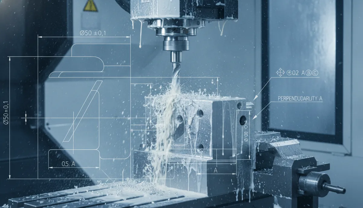
Ready to Master CNC GD&T?
Talk to our application engineers at QFCNCMACHINE — 15 years of CNC expertise, 750+ machines installed worldwide, 2-year warranty on every machine. Get a free GD&T reference guide and manufacturing consultation today.
References
- Mordor Intelligence, CNC Machines Market Size, Share & Growth Trends Report, 2025. https://www.mordorintelligence.com/industry-reports/cnc-machines-market
- Grand View Research, Computer Numerical Control Machines Market Report, 2023. https://www.grandviewresearch.com/industry-analysis/computer-numerical-controls-cnc-market
- Research Nester, CNC Machine Market Size, Share & Trends Report 2035, 2025. https://www.researchnester.com/reports/computer-numerical-control-machine-market/5889
- ASME International, ASME Y14.5-2018: Dimensioning and Tolerancing Standard, 2018. https://www.asme.org/codes-standards/find-codes-standards/y14-5-dimensioning-tolerancing